DDC2 / | Digital Display Wall Clock Guide | Page 44 |
|
|
|
Appendix B - DDC2-RS-24 / DDC4-RS-24 Wiring
The
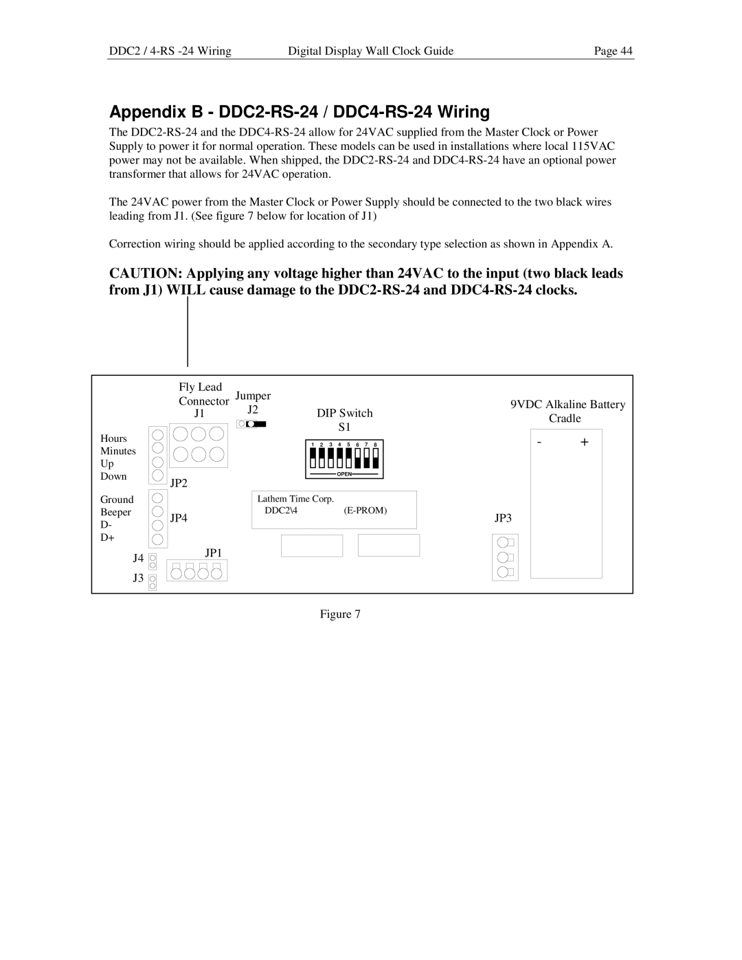
The 24VAC power from the Master Clock or Power Supply should be connected to the two black wires leading from J1. (See figure 7 below for location of J1)
Correction wiring should be applied according to the secondary type selection as shown in Appendix A.
CAUTION: Applying any voltage higher than 24VAC to the input (two black leads from J1) WILL cause damage to the
Hours
Minutes
Up
Down
Ground
Beeper
D-
D+
J4
J3
Fly Lead |
|
|
|
|
|
|
|
|
Connector Jumper |
|
|
|
|
|
|
| |
J1 | J2 | DIP Switch |
| |||||
|
| |||||||
|
|
|
| S1 |
|
|
| |
| 1 | 2 | 3 | 4 | 5 | 6 | 7 | 8 |
|
|
|
| OPEN |
|
|
| |
JP2
Lathem Time Corp.
DDC2\4(E-PROM)
JP4
JP1
9VDC Alkaline Battery
Cradle
-+
JP3
Figure 7