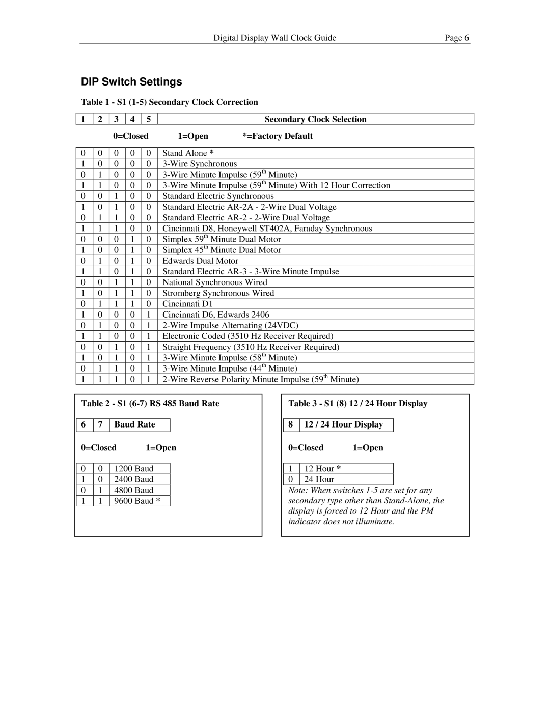
Digital Display Wall Clock Guide | Page 6 |
|
|
DIP Switch Settings
Table 1 - S1
1 | 2 | 3 | 4 | 5 |
| Secondary Clock Selection |
|
|
| 0=Closed | 1=Open | *=Factory Default | |||
|
|
|
|
|
|
|
|
0 | 0 | 0 | 0 | 0 | Stand Alone * |
|
|
1 | 0 | 0 | 0 | 0 |
|
| |
0 | 1 | 0 | 0 | 0 | |||
1 | 1 | 0 | 0 | 0 | |||
0 | 0 | 1 | 0 | 0 | Standard Electric Synchronous | ||
1 | 0 | 1 | 0 | 0 | Standard Electric | ||
0 | 1 | 1 | 0 | 0 | Standard Electric | ||
1 | 1 | 1 | 0 | 0 | Cincinnati D8, Honeywell ST402A, Faraday Synchronous | ||
0 | 0 | 0 | 1 | 0 | Simplex 59th Minute Dual Motor | ||
1 | 0 | 0 | 1 | 0 | Simplex 45th Minute Dual Motor | ||
0 | 1 | 0 | 1 | 0 | Edwards Dual Motor |
|
|
1 | 1 | 0 | 1 | 0 | Standard Electric | ||
0 | 0 | 1 | 1 | 0 | National Synchronous Wired | ||
1 | 0 | 1 | 1 | 0 | Stromberg Synchronous Wired | ||
0 | 1 | 1 | 1 | 0 | Cincinnati D1 |
|
|
1 | 0 | 0 | 0 | 1 | Cincinnati D6, Edwards 2406 | ||
0 | 1 | 0 | 0 | 1 | |||
1 | 1 | 0 | 0 | 1 | Electronic Coded (3510 Hz Receiver Required) | ||
0 | 0 | 1 | 0 | 1 | Straight Frequency (3510 Hz Receiver Required) | ||
1 | 0 | 1 | 0 | 1 | |||
0 | 1 | 1 | 0 | 1 | |||
1 | 1 | 1 | 0 | 1 | |||
Table 2 - S1
67 Baud Rate
0=Closed 1=Open
00 1200 Baud
10 2400 Baud
01 4800 Baud
11 9600 Baud *
Table 3 - S1 (8) 12 / 24 Hour Display
812 / 24 Hour Display
0=Closed 1=Open
112 Hour *
0 24 Hour
Note: When switches