CARE AND OPERATION
BLOWER SYSTEM
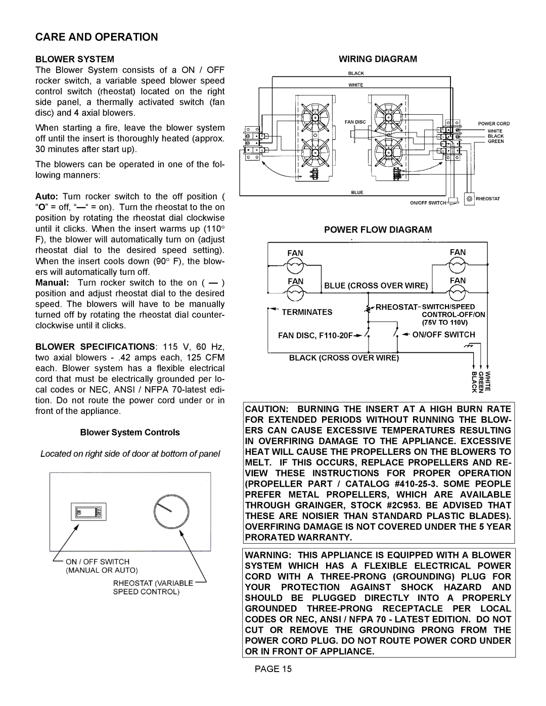
The Blower System consists of a ON / OFF rocker switch, a variable speed blower speed control switch (rheostat) located on the right side panel, a thermally activated switch (fan disc) and 4 axial blowers.
When starting a fire, leave the blower system off until the insert is thoroughly heated (approx. 30 minutes after start up).
The blowers can be operated in one of the fol- lowing manners:
Auto: Turn rocker switch to the off position ( “O” = off,
Manual: Turn rocker switch to the on ( — ) position and adjust rheostat dial to the desired speed. The blowers will have to be manually turned off by rotating the rheostat dial counter- clockwise until it clicks.
BLOWER SPECIFICATIONS: 115 V, 60 Hz, two axial blowers
Blower System Controls
Located on right side of door at bottom of panel
WIRING DIAGRAM
POWER FLOW DIAGRAM
CAUTION: BURNING THE INSERT AT A HIGH BURN RATE FOR EXTENDED PERIODS WITHOUT RUNNING THE BLOW- ERS CAN CAUSE EXCESSIVE TEMPERATURES RESULTING IN OVERFIRING DAMAGE TO THE APPLIANCE. EXCESSIVE HEAT WILL CAUSE THE PROPELLERS ON THE BLOWERS TO MELT. IF THIS OCCURS, REPLACE PROPELLERS AND RE- VIEW THESE INSTRUCTIONS FOR PROPER OPERATION (PROPELLER PART / CATALOG
WARNING: THIS APPLIANCE IS EQUIPPED WITH A BLOWER SYSTEM WHICH HAS A FLEXIBLE ELECTRICAL POWER CORD WITH A
PAGE 15
