System Diagnostic Module
4HP18LT units contain a diagnostic module for troubleshouting heat pump system failures. By monitoring and analyzing data from the compressor and thermostat demand, the module can accurately detect the cause of electrical and system related failure without any sensors. If a system problem occurs, a flashing LED indicator communicates the failure code.
LED Description
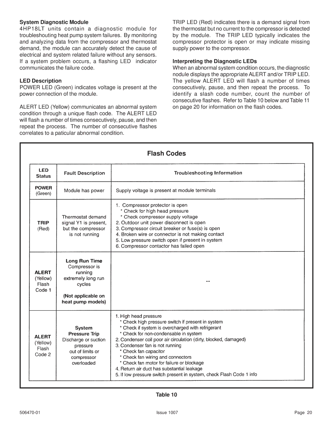
POWER LED (Green) indicates voltage is present at the power connection of the module.
ALERT LED (Yellow) communicates an abnormal system condition through a unique flash code. The ALERT LED will flash a number of times consecutively, pause, and then repeat the process. The number of consecutive flashes correlates to a paticular abnormal condition.
TRIP LED (Red) indicates there is a demand signal from the thermostat but no current to the compressor is detected by the module. The TRIP LED typically indicates the compressor protector is open or may indicate missing supply power to the compressor.
Interpreting the Diagnostic LEDs
When an abnormal system condition occurs, the diagnostic nodule displays the appropriate ALERT and/or TRIP LED. The yellow ALERT LED will flash a number of times consecutively, pause, and then repeat the process. To identify a slash code number, count the number of consecutive flashes. Refer to Table 10 below and Table 11 on page 20 for information on the flash codes.
Flash Codes
Table 10
Issue 1007 | Page 20 |