Placement
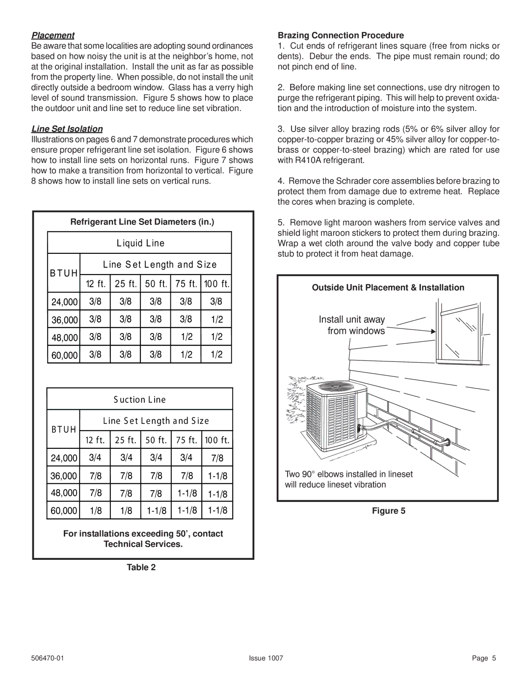
Be aware that some localities are adopting sound ordinances based on how noisy the unit is at the neighbor’s home, not at the original installation. Install the unit as far as possible from the property line. When possible, do not install the unit directly outside a bedroom window. Glass has a verry high level of sound transmission. Figure 5 shows how to place the outdoor unit and line set to reduce line set vibration.
Line Set Isolation
Illustrations on pages 6 and 7 demonstrate procedures which ensure proper refrigerant line set isolation. Figure 6 shows how to install line sets on horizontal runs. Figure 7 shows how to make a transition from horizontal to vertical. Figure 8 shows how to install line sets on vertical runs.
Refrigerant Line Set Diameters (in.)
Liquid Line
Line Set Length and Size
BTUH
| 12 ft. 25 ft. 50 ft. 75 ft. 100 ft. | ||||
24,000 | 3/8 | 3/8 | 3/8 | 3/8 | 3/8 |
36,000 | 3/8 | 3/8 | 3/8 | 3/8 | 1/2 |
48,000 | 3/8 | 3/8 | 3/8 | 1/2 | 1/2 |
60,000 3/8 3/8 3/8 1/2 1/2
S uction Line
Line S et Length and S ize
B T UH
| 12 ft. 25 ft. 50 ft. 75 ft. 100 ft. | ||||
24,000 | 3/4 | 3/4 | 3/4 | 3/4 | 7/8 |
36,000 | 7/8 | 7/8 | 7/8 | 7/8 | |
48,000 | 7/8 | 7/8 | 7/8 | ||
60,000 1/8 1/8 1-1/8 1-1/8 1-1/8
For installations exceeding 50’, contact
Technical Services.
Table 2
Brazing Connection Procedure
1.Cut ends of refrigerant lines square (free from nicks or dents). Debur the ends. The pipe must remain round; do not pinch end of line.
2.Before making line set connections, use dry nitrogen to purge the refrigerant piping. This will help to prevent oxida- tion and the introduction of moisture into the system.
3.Use silver alloy brazing rods (5% or 6% silver alloy for
4.Remove the Schrader core assemblies before brazing to protect them from damage due to extreme heat. Replace the cores when brazing is complete.
5.Remove light maroon washers from service valves and shield light maroon stickers to protect them during brazing. Wrap a wet cloth around the valve body and copper tube stub to protect it from heat damage.
Outside Unit Placement & Installation
Install unit away from windows
Two 90° elbows installed in lineset will reduce lineset vibration
Figure 5
Issue 1007 | Page 5 |