Gas Piping |
|
|
|
|
|
|
|
| 4 − | The piping should be sloped 1/4 inch (6.4 mm) per 15 | |||||||||
|
|
|
|
|
|
|
|
| feet (4.57 m) upward toward the meter from the fur- | ||||||||||
Gas supply piping should not allow more than 0.5"W.C. drop |
|
|
|
| |||||||||||||||
|
|
| nace. The piping must be supported at proper intervals | ||||||||||||||||
in pressure between gas meter and unit. Supply gas pipe |
|
|
| ||||||||||||||||
|
|
| [every 8 to 10 feet (2.44 to 3.01 m)] with suitable hang- | ||||||||||||||||
must not be smaller than unit gas connection. |
|
|
|
|
|
| |||||||||||||
|
|
|
|
|
| ers or straps. Install a drip leg in vertical pipe runs to the | |||||||||||||
|
|
|
|
|
|
|
|
|
|
|
| ||||||||
|
|
|
|
|
|
|
|
|
|
|
| unit. |
|
|
|
|
|
| |
|
| CAUTION |
|
|
|
|
|
|
|
|
|
|
|
|
| ||||
|
|
|
|
|
|
|
| 5 − | A 1/8" N.P.T. plugged tap or pressure post | is located | |||||||||
|
|
|
|
|
|
|
|
|
|
|
| on the gas valve to facilitate test gauge connection. | |||||||
If a flexible gas connector is required or allowed by |
|
|
|
|
| ||||||||||||||
|
|
|
|
|
|
|
|
|
|
|
| ||||||||
the authority that has jurisdiction, black iron pipe |
|
|
|
| See figure 35. |
|
|
| |||||||||||
shall be installed at the gas valve and extend outside |
|
|
| 6 − In some localities, codes may require the installation of | |||||||||||||||
the furnace cabinet. The flexible connector can then |
|
|
|
| |||||||||||||||
|
|
|
| a manual main | |||||||||||||||
be added between the black iron pipe and the gas |
|
|
|
|
| ||||||||||||||
|
|
|
|
|
|
|
|
|
|
|
| ||||||||
supply line. |
|
|
|
|
|
|
|
|
| the installer) external to the unit. The union must be of | |||||||||
|
|
|
|
|
|
|
|
|
|
|
| the ground joint type. |
|
|
| ||||
Gas Supply |
|
|
|
|
|
|
|
|
|
|
|
| |||||||
|
|
|
|
|
|
|
|
|
|
|
|
|
|
|
|
| |||
1 − This unit is shipped standard for left or right side instal- |
|
|
|
|
|
|
|
|
|
|
| ||||||||
|
|
|
|
|
| IMPORTANT |
| ||||||||||||
| lation of gas piping (or top entry in horizontal applica- |
|
|
|
|
|
|
| |||||||||||
|
|
|
|
|
|
|
|
|
|
|
| ||||||||
| tions). Connect the gas supply to the piping assembly. |
|
|
|
|
|
|
|
|
|
|
| |||||||
2 − | When connecting the gas supply piping, consider fac- |
|
| Compounds used on threaded joints of gas piping | |||||||||||||||
|
| ||||||||||||||||||
| tors such as length of run, number of fittings, and fur- |
|
| must be resistant to the actions of liquified petro- | |||||||||||||||
|
|
| leum gases. |
|
|
|
|
| |||||||||||
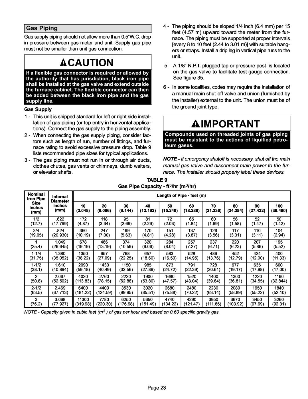
| nace rating to avoid excessive pressure drop. Table 9 |
|
|
|
|
|
|
| |||||||||||
| lists recommended pipe sizes for typical applications. |
|
|
|
|
|
|
|
|
|
|
| |||||||
3 − | The gas piping must not run in or through air ducts, |
|
| NOTE − If emergency shutoff is necessary, shut off the main | |||||||||||||||
| clothes chutes, gas vents or chimneys, dumb waiters, |
|
| manual gas valve and disconnect main power to the fur- | |||||||||||||||
| or elevator shafts. |
|
|
|
|
|
|
|
| nace. The installer should properly label these devices. | |||||||||
|
|
|
|
|
| TABLE 9 |
|
|
|
|
|
|
|
| |||||
|
|
|
|
| Gas Pipe Capacity − ft3/hr (m3/hr) |
|
|
|
|
| |||||||||
Nominal | Internal |
|
|
|
|
|
| Length of Pipe − feet (m) |
|
|
| ||||||||
Iron Pipe |
|
|
|
|
|
|
|
|
| ||||||||||
|
|
|
|
|
|
|
|
|
|
|
|
|
|
|
|
| |||
Diameter |
|
|
|
|
|
|
|
|
|
|
|
|
|
|
|
|
| ||
| Size |
|
|
|
|
|
|
|
|
|
|
|
|
|
|
|
|
| |
| inches | 10 | 20 | 30 | 40 |
|
|
| 50 |
|
| 60 |
| 70 | 80 | 90 | 100 | ||
inches |
|
|
|
|
|
| |||||||||||||
(mm) | (3.048) | (6.096) | (9.144) | (12.192) |
| (15.240) |
| (18.288) |
| (21.336) | (24.384) | (27.432) | (30.480) | ||||||
| (mm) |
|
|
| |||||||||||||||
|
|
|
|
|
|
|
|
|
|
|
|
|
|
|
|
|
|
| |
|
|
|
|
|
|
|
|
|
|
|
|
|
|
|
|
|
|
| |
| 1/2 | .622 | 172 | 118 | 95 | 81 |
|
|
| 72 |
|
| 65 |
| 60 | 56 | 52 | 50 | |
| (12.7) | (17.799) | (4.87) | (3.34) | (2.69) | (2.29) |
| (2.03) |
| (1.84) |
| (1.69) | (1.58) | (1.47) | (1.42) | ||||
|
|
|
|
|
|
|
|
|
|
|
|
|
|
|
|
| |||
| 3/4 | .824 | 360 | 247 | 199 | 170 |
|
| 151 |
| 137 |
| 126 | 117 | 110 | 104 | |||
(19.05) | (20.930) | (10.19) | (7.00) | (5.63) | (4.81) |
| (4.28) |
| (3.87) |
| (3.56) | (3.31) | (3.11) | (2.94) | |||||
|
|
|
|
|
|
|
|
|
|
|
|
|
|
|
|
| |||
| 1 | 1.049 | 678 | 466 | 374 | 320 |
|
| 284 |
| 257 |
| 237 | 220 | 207 | 195 | |||
| (25.4) | (26.645) | (19.19) | (13.19) | (10.59) | (9.06) |
| (8.04) |
| (7.27) |
| (6.71) | (6.23) | (5.86) | (5.52) | ||||
|
|
|
|
|
|
|
|
|
|
|
|
|
|
|
|
| |||
| 1−1/4 | 1.380 | 1350 | 957 | 768 | 657 |
|
| 583 |
| 528 |
| 486 | 452 | 424 | 400 | |||
(31.75) | (35.052) | (38.22) | (27.09) | (22.25) | (18.60) |
| (16.50) |
| (14.95) |
| (13.76) | (12.79) | (12.00) | (11.33) | |||||
|
|
|
|
|
|
|
|
|
|
|
|
|
|
|
|
| |||
| 1−1/2 | 1.610 | 2090 | 1430 | 1150 | 985 |
|
| 873 |
| 791 |
| 728 | 677 | 635 | 600 | |||
| (38.1) | (40.894) | (59.18) | (40.49) | (32.56) | (27.89) |
| (24.72) |
| (22.39) |
| (20.61) | (19.17) | (17.98) | (17.00) | ||||
|
|
|
|
|
|
|
|
|
|
|
|
|
|
|
| ||||
| 2 | 2.067 | 4020 | 2760 | 2220 | 1900 |
| 1680 |
| 1520 |
| 1400 | 1300 | 1220 | 1160 | ||||
| (50.8) | (52.502) | (113.83) | (78.15) | (62.86) | (53.80) |
| (47.57) |
| (43.04) |
| (39.64) | (36.81) | (34.55) | (32.844) | ||||
|
|
|
|
|
|
|
|
|
|
|
|
|
|
|
| ||||
| 2−1/2 | 2.469 | 6400 | 4400 | 3530 | 3020 |
| 2680 |
| 2480 |
| 2230 | 2080 | 1950 | 1840 | ||||
| (63.5) | (67.713) | (181.22) | (124.59) | (99.95) | (85.51) |
| (75.88) |
| (70.22) |
| (63.14) | (58.89) | (55.22) | (52.10) | ||||
|
|
|
|
|
|
|
|
|
|
|
|
|
|
|
| ||||
| 3 | 3.068 | 11300 | 7780 | 6250 | 5350 |
| 4740 |
| 4290 |
| 3950 | 3670 | 3450 | 3260 | ||||
| (76.2) | (77.927) | (319.98) | (220.30) | (176.98) | (151.49) |
| (134.22) |
| (121.47) |
| (111.85) | (103.92) | (97.69) | (92.31) | ||||
|
|
|
|
|
|
|
|
|
|
|
|
|
|
|
|
|
|
|
|
NOTE − Capacity given in cubic feet (m3 ) of gas per hour and based on 0.60 specific gravity gas.
Page 23