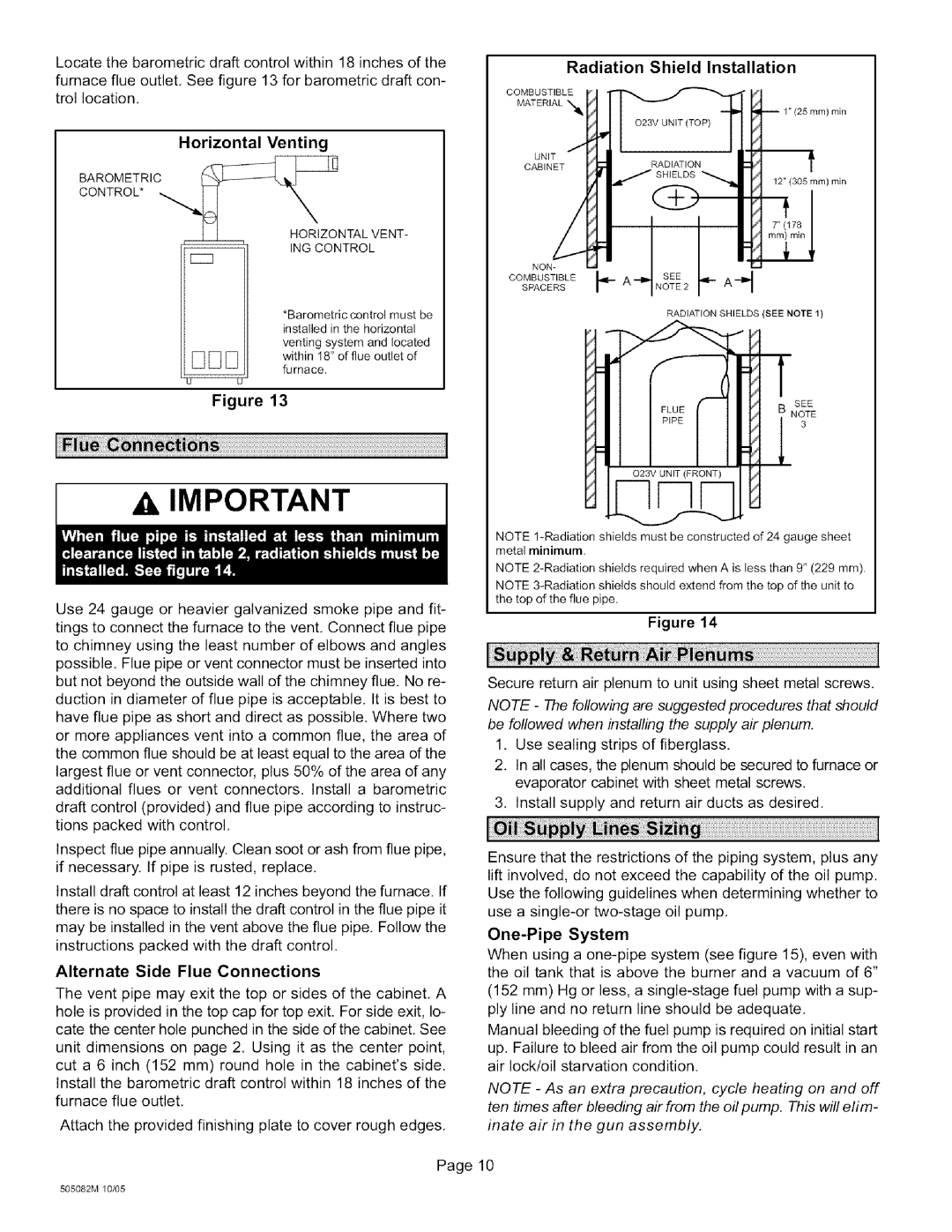
Locate the barometric draft control within 18 inches of the

furnace flue outlet, See figure 13 for barometric draft con- trol location.

Horizontal Venting

BAROMETRIC

CONTROL*


HORIZONTAL VENT-

--

ING CONTROL

CC3

*Barometric control must be installed in the horizontal

venting system and located within 18" of flue outlet of furnace.

QU

Figure 13

Radiation Shield Installation

COMBUSTIBLE

MATERIAL "_

UNIT

t

CABINET


12" (305 ram) rain

I I

NoN1l.

COMBUST,BLEISPACERS. A NOTESEE2 A

RADIATION SHIELDS (SEE NOTE 1)

SEE

NOTE 3

AIMPORTANT

Use 24 gauge or heavier galvanized smoke pipe and fit- tings to connect the furnace to the vent, Connect flue pipe to chimney using the least number of elbows and angles possible. Flue pipe or vent connector must be inserted into but not beyond the outside wall of the chimney flue. No re- duction in diameter of flue pipe is acceptable. It is best to have flue pipe as short and direct as possible. Where two or more appliances vent into a common flue, the area of the common flue should be at least equal to the area of the largest flue or vent connector, plus 50% of the area of any additional flues or vent connectors. Install a barometric draft control (provided) and flue pipe according to instruc- tions packed with control,

Inspect flue pipe annually. Clean soot or ash from flue pipe, if necessary. If pipe is rusted, replace,

Install draft control at least 12 inches beyond the furnace. If there is no space to install the draft control in the flue pipe it may be installed in the vent above the flue pipe, Follow the instructions packed with the draft control,

Alternate Side Flue Connections

The vent pipe may exit the top or sides of the cabinet, A hole is provided in the top cap for top exit. For side exit, lo- cate the center hole punched in the side of the cabinet, See unit dimensions on page 2. Using it as the center point, cut a 6 inch (152 mm) round hole in the cabinet's side. Install the barometric draft control within 18 inches of the furnace flue outlet,

Attach the provided finishing plate to cover rough edges.

NOTE 1-Radiation shields must be constructed of 24 gauge sheet metal minimum.

NOTE 2-Radiation shields required when A is less than 9" (229 mm).

NOTE 3-Radiation shields should extend from the top of the unit to the top of the flue pipe.

Figure 14

Secure return air plenum to unit using sheet metal screws, NOTE - The following are suggested procedures that should be followed when installing the supply air plenum,

1.Use sealing strips of fiberglass.

2.In all cases, the plenum should be secured to furnace or evaporator cabinet with sheet metal screws.

3.Install supply and return air ducts as desired.

Ensure that the restrictions of the piping system, plus any lift involved, do not exceed the capability of the oil pump, Use the following guidelines when determining whether to use a single-or two-stage oil pump.

One-Pipe System

When using a one-pipe system (see figure 15), even with the oil tank that is above the burner and a vacuum of 6"

(152 mm) Hg or less, a single-stage fuel pump with a sup- ply line and no return line should be adequate.

Manual bleeding of the fuel pump is required on initial start

up. Failure to bleed air from the oil pump could result in an air lock/oil starvation condition.

NOTE - As an extra precaution, cycle heating on and off ten times after bleeding air from the oil pump. This will elim- inate air in the gun assembly.

Page 10

505082M 10/05

Page 10
Image 10
Lennox International Inc O23V-90, O23V5-140, O23V5-154 Radiation Shield Installation, Alternate Side Flue Connections

O23V2-90, O23V-90, O23V4-105, O23V5-154, O23V3-70 specifications

Lennox International Inc. is a leading provider of innovative climate control solutions, widely recognized for its high-quality heating, ventilation, and air conditioning (HVAC) systems. Among its varied product line, the O23 series exemplifies Lennox's commitment to energy efficiency, performance, and user-friendly technology.

The O23V2-90, O23V3-120, O23V3-90, O23V4-105, and O23V2-70 are advanced models of the O23 series, designed specifically for residential settings. Each model offers unique specifications tailored to meet diverse customer needs.

These units are equipped with cutting-edge inverter technology, which allows for precise control of air temperature and flow. By adjusting the compressor speed, these systems optimize energy consumption while maintaining comfort. This variable-speed operation minimizes energy waste and significantly reduces utility bills, a key advantage for homeowners seeking efficient solutions.

The O23V3-120 stands out for its high cooling and heating capacities, making it ideal for larger homes or commercial spaces. Meanwhile, the O23V2-70 model is designed for smaller applications, ensuring that even modest-sized spaces can benefit from Lennox quality. Each model also features robust insulation and construction, enhancing durability and performance over time.

Incorporating smart technology, these units come with Wi-Fi connectivity, empowering users to manage their home’s temperature remotely through a smartphone app. The integration with smart home systems further enhances the user experience, providing convenience and efficiency right at your fingertips.

Quiet operation is another hallmark of the O23 series. Each model is engineered to reduce sound levels, ensuring that comfort does not compromise peace within the home.

Additionally, these units are designed with environmentally-friendly refrigerants, aligning with global sustainability efforts. This focus on eco-conscious technology not only adheres to regulatory standards but also appeals to environmentally-aware consumers.

Overall, Lennox O23 series models showcase a blend of advanced technology, efficient performance, and user-friendly features, embodying the brand’s commitment to excellence in climate control solutions. For homeowners and businesses alike, investing in these models translates to greater comfort, cost savings, and a reduced ecological footprint.