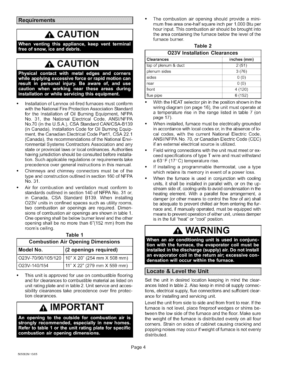
O23V2-90, O23V-90, O23V4-105, O23V5-154, O23V3-70 specifications
Lennox International Inc. is a leading provider of innovative climate control solutions, widely recognized for its high-quality heating, ventilation, and air conditioning (HVAC) systems. Among its varied product line, the O23 series exemplifies Lennox's commitment to energy efficiency, performance, and user-friendly technology.The O23V2-90, O23V3-120, O23V3-90, O23V4-105, and O23V2-70 are advanced models of the O23 series, designed specifically for residential settings. Each model offers unique specifications tailored to meet diverse customer needs.
These units are equipped with cutting-edge inverter technology, which allows for precise control of air temperature and flow. By adjusting the compressor speed, these systems optimize energy consumption while maintaining comfort. This variable-speed operation minimizes energy waste and significantly reduces utility bills, a key advantage for homeowners seeking efficient solutions.
The O23V3-120 stands out for its high cooling and heating capacities, making it ideal for larger homes or commercial spaces. Meanwhile, the O23V2-70 model is designed for smaller applications, ensuring that even modest-sized spaces can benefit from Lennox quality. Each model also features robust insulation and construction, enhancing durability and performance over time.
Incorporating smart technology, these units come with Wi-Fi connectivity, empowering users to manage their home’s temperature remotely through a smartphone app. The integration with smart home systems further enhances the user experience, providing convenience and efficiency right at your fingertips.
Quiet operation is another hallmark of the O23 series. Each model is engineered to reduce sound levels, ensuring that comfort does not compromise peace within the home.
Additionally, these units are designed with environmentally-friendly refrigerants, aligning with global sustainability efforts. This focus on eco-conscious technology not only adheres to regulatory standards but also appeals to environmentally-aware consumers.
Overall, Lennox O23 series models showcase a blend of advanced technology, efficient performance, and user-friendly features, embodying the brand’s commitment to excellence in climate control solutions. For homeowners and businesses alike, investing in these models translates to greater comfort, cost savings, and a reduced ecological footprint.

