ADJUST

The ADJUST pins allow the motor to run at normal speed, approximately 15% higher than normal speed, or 15% low- er than normal speed. Table 6 gives three rows--NORM, (+), and (-) with their respective CFM volumes. Notice that the normal <'NORM"adjustment setting for cool speed position C in table 6 is 800 CFM The "(+)" adjustment set- ting for that position is 920 CFM (115% of 800 CFM) and the "(-)" adjustment setting is 680 CFM (85% of 800 CFM). After the adjustment setting has been determined, choose

the remaining speed settings from those offered in the table in that row.

The TEST pin is available to bypass the blower control and run the motor at approximately 70% to make sure that the motor is operational. This is used mainly in troubleshoot- ing. The G terminal must be energized for the motor to run.

COOL (single-stage systems)

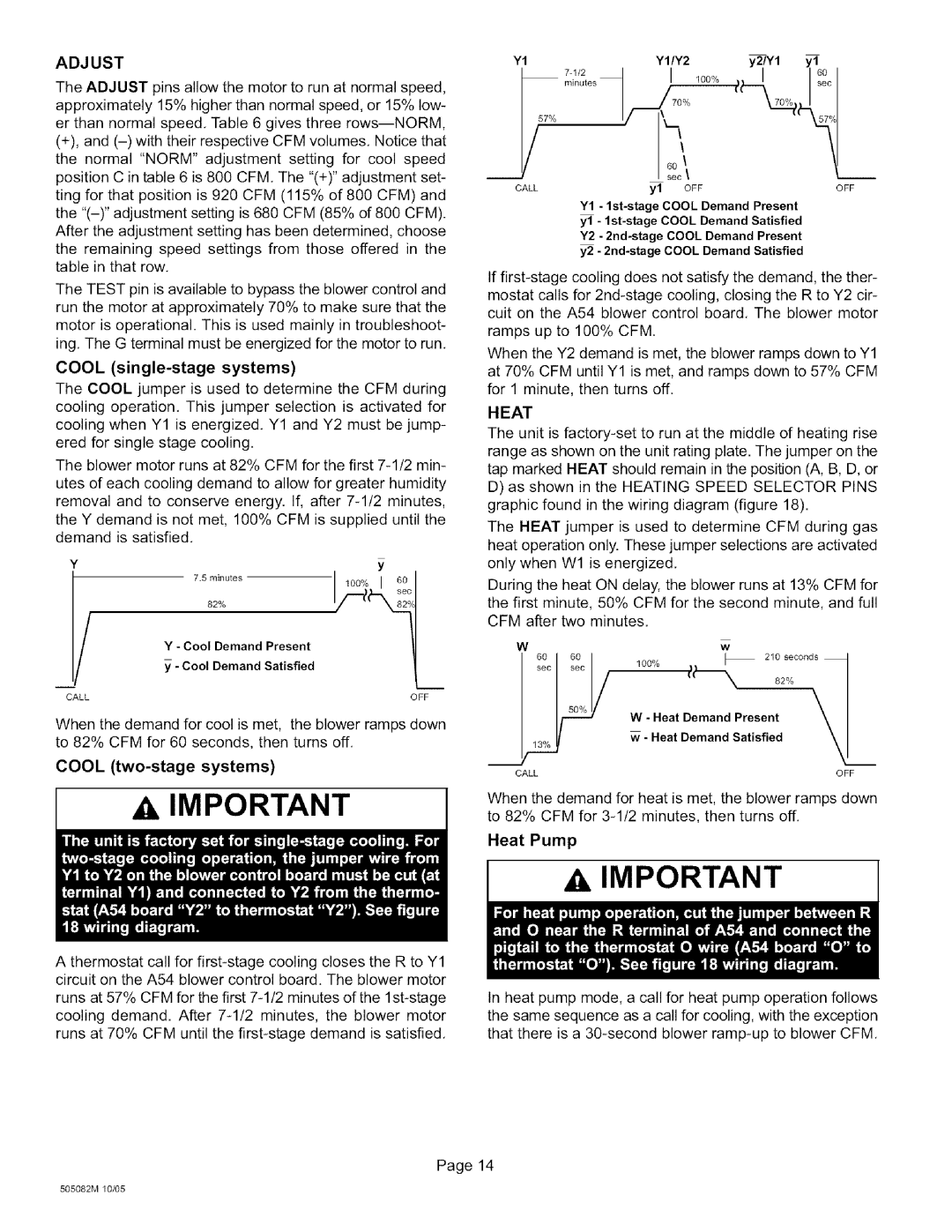
The COOL jumper is used to determine the CFM during cooling operation. This jumper selection is activated for cooling when Y1 is energized. Y1 and Y2 must be jump- ered for single stage cooling.

The blower motor runs at 82% CFM for the first 7-1/2 min- utes of each cooling demand to allow for greater humidity removal and to conserve energy. If, after 7-1/2 minutes, the Y demand is not met, 100% CFM is supplied until the demand is satisfied.

Y1

7N/2

YI/Y2

y2/Y1

yl

y57°/°

minutes 1_i_-i°60


\y° 100°/°

(_t_ I7_o

60

i


sec

\


i

CALL


yl

OFF


OFF

Y1 - 1st-stage COOL Demand Present yl - 1st-stage COOL Demand Satisfied Y2 - 2nd-stage COOL Demand Present y2 - 2nd-stage COOL Demand Satisfied

If first-stage cooling does not satisfy the demand, the ther- mostat calls for 2nd-stage cooling, closing the R to Y2 cir- cuit on the A54 blower control board. The blower motor ramps up to 100% CFM

When the Y2 demand is met, the blower ramps down to Y1 at 70% CFM until Y1 is met, and ramps down to 57% CFM for 1 minute, then turns off.

HEAT

The unit is factory-set to run at the middle of heating rise range as shown on the unit rating plate. The jumper on the tap marked HEAT should remain in the position (A, B, D, or

D)as shown in the HEATING SPEED SELECTOR PINS graphic found in the wiring diagram (figure 18).

The HEAT jumper is used to determine CFM during gas heat operation only. These jumper selections are activated

Y

/

i

7.Sminutes

] 100% I 50


so(

Y - Cool Demand Present

- Cool Demand Satisfied

only when W1 is energized.

During the heat ON delay, the blower runs at 13% CFM for the first minute, 50% CFM for the second minute, and full CFM after two minutes.

Ww

sec

sec

100%

_

_

210 seconds

82%

\

CALL

OFF

When the demand for cool is met, the blower ramps down to 82% CFM for 60 seconds, then turns off.

COOL (two-stage systems)

IMPORTANT

60 61_W - Heat Demand Present

- Heat Demand Satisfied \

CALL

OFF

When the demand for heat is met, the blower ramps down to 82% CFM for 3-1/2 minutes, then turns off.

Heat Pump

IMPORTANT

A thermostat call for first-stage cooling closes the R to Y1 circuit on the A54 blower control board. The blower motor

runs at 57% CFM for the first 7-1/2 minutes of the 1st-stage cooling demand. After 7-1/2 minutes, the blower motor runs at 70% CFM until the first-stage demand is satisfied.

In heat pump mode, a call for heat pump operation follows the same sequence as a call for cooling, with the exception that there is a 30-second blower ramp-up to blower CFM

Page 14

505082M 10/05

Page 14
Image 14
Lennox International Inc O23V3-70, O23V5-140, O23V5-154, O23V-70, O23V4-120, O23V-105, O23V-120, O23V4-105 Adjust, Heat Pump

O23V2-90, O23V-90, O23V4-105, O23V5-154, O23V3-70 specifications

Lennox International Inc. is a leading provider of innovative climate control solutions, widely recognized for its high-quality heating, ventilation, and air conditioning (HVAC) systems. Among its varied product line, the O23 series exemplifies Lennox's commitment to energy efficiency, performance, and user-friendly technology.

The O23V2-90, O23V3-120, O23V3-90, O23V4-105, and O23V2-70 are advanced models of the O23 series, designed specifically for residential settings. Each model offers unique specifications tailored to meet diverse customer needs.

These units are equipped with cutting-edge inverter technology, which allows for precise control of air temperature and flow. By adjusting the compressor speed, these systems optimize energy consumption while maintaining comfort. This variable-speed operation minimizes energy waste and significantly reduces utility bills, a key advantage for homeowners seeking efficient solutions.

The O23V3-120 stands out for its high cooling and heating capacities, making it ideal for larger homes or commercial spaces. Meanwhile, the O23V2-70 model is designed for smaller applications, ensuring that even modest-sized spaces can benefit from Lennox quality. Each model also features robust insulation and construction, enhancing durability and performance over time.

Incorporating smart technology, these units come with Wi-Fi connectivity, empowering users to manage their home’s temperature remotely through a smartphone app. The integration with smart home systems further enhances the user experience, providing convenience and efficiency right at your fingertips.

Quiet operation is another hallmark of the O23 series. Each model is engineered to reduce sound levels, ensuring that comfort does not compromise peace within the home.

Additionally, these units are designed with environmentally-friendly refrigerants, aligning with global sustainability efforts. This focus on eco-conscious technology not only adheres to regulatory standards but also appeals to environmentally-aware consumers.

Overall, Lennox O23 series models showcase a blend of advanced technology, efficient performance, and user-friendly features, embodying the brand’s commitment to excellence in climate control solutions. For homeowners and businesses alike, investing in these models translates to greater comfort, cost savings, and a reduced ecological footprint.