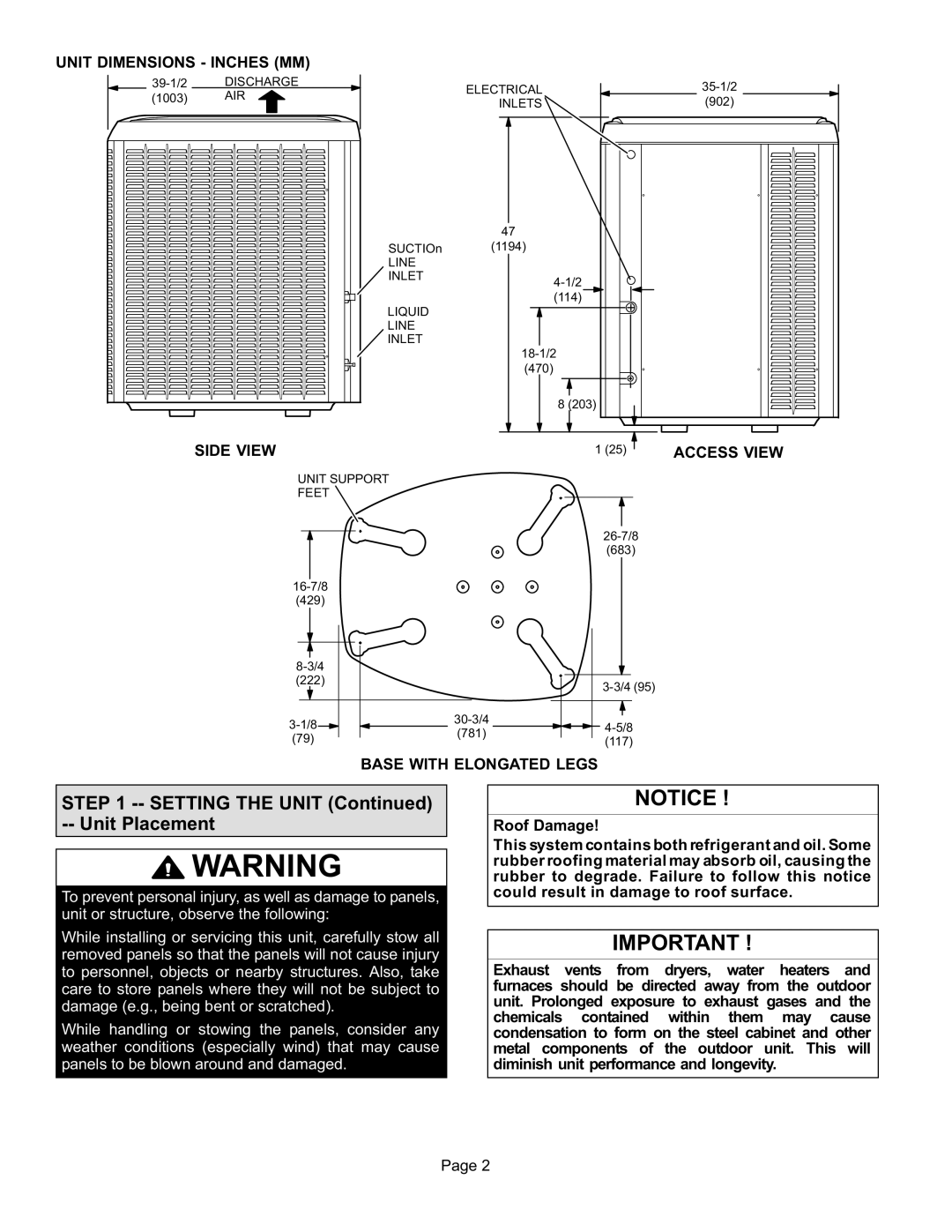
Dave Lennox Signature Collection XC21 System, XC21 specifications
Lennox International Inc. has long been synonymous with innovative heating and cooling solutions. One of the standout products in their lineup is the Dave Lennox Signature Collection XC21 System, a central air conditioning unit renowned for its remarkable efficiency, advanced technology, and superior performance.The XC21 features Lennox’s proprietary Signature Series components, ensuring that homeowners receive top-tier comfort with energy-saving capabilities. One of the main highlights of the XC21 is its impressive SEER (Seasonal Energy Efficiency Ratio) rating of up to 21. This high rating signifies exceptional energy efficiency, allowing homeowners to save significantly on energy bills while maintaining a comfortable indoor environment.
One of the key technologies incorporated into the XC21 is the variable-speed compressor. This feature enables the system to adjust its cooling output in response to the current temperature and humidity levels, providing optimal comfort without excessive energy consumption. The variable-speed operation allows for quieter performance, with sound levels as low as 65 decibels, making it one of the quietest systems available.
Furthermore, the XC21 is designed with the Advanced Energy Efficiency feature, which enhances its capability to regulate energy usage intelligently. This is complemented by the Smart Away feature, allowing the unit to enter energy-saving mode when the homeowner is away, ensuring that no energy is wasted during times of inactivity.
Additionally, the XC21 is built with durable and high-quality materials, including a galvanized steel cabinet that resists rust and corrosion, ensuring longevity and consistent performance in varied weather conditions. It also includes a unique design that allows for easier maintenance and serviceability, minimizing downtime and repair costs.
The XC21 system is compatible with the iComfort S30 smart thermostat, which offers advanced climate control capabilities through Wi-Fi connectivity. This feature allows users to manage their home’s heating and cooling system remotely, providing convenience and enhancing energy efficiency.
In summary, the Dave Lennox Signature Collection XC21 System exemplifies Lennox International Inc.’s commitment to cutting-edge technology, energy efficiency, and customer satisfaction. Its innovative features, high energy efficiency ratings, and user-friendly characteristics make it an excellent choice for homeowners looking to enhance their comfort while reducing energy expenses.

