STEP 2 −− REFRIGERANT PIPING −− Removing Existing Indoor Metering Device


TYPICAL EXISTING FIXED ORIFICE


TYPICAL EXISTING EXPANSION VALVE REMOVAL

1A

REMOVAL PROCEDURE

OR

1BPROCEDURE (UNCASED COIL SHOWN)

(UNCASED COIL SHOWN)


STUB END


DISTRIBUTOR TUBES


TWO−PIECE PATCH PLATE

LIQUID LINE


(UNCASED COIL ONLY)


ORIFICE

EXPANSION


LIQUID LINE ORIFICE HOUSING


DISTRIBUTOR

HOUSING

VALVE


TEFLON® RING


TUBES


TEFLON®


RING


FIXED ORIFICE


BRASS NUT


TEFLON®


RING

SENSING


LINE

DISTRIBUTOR ASSEMBLY

REMOVE AND DISCARD

WHITE TEFLON® SEAL

(IF PRESENT) LIQUID LINE ASSEMBLY (INCLUDES STRAINER)

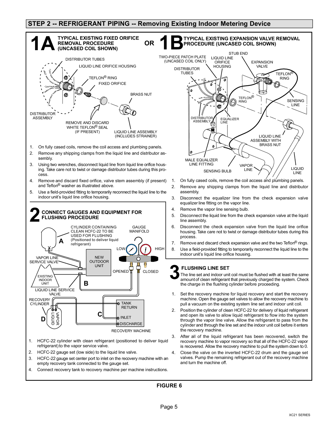
1.On fully cased coils, remove the coil access and plumbing panels.

2.Remove any shipping clamps from the liquid line and distributor as- sembly.

3.Using two wrenches, disconnect liquid line from liquid line orifice hous- ing. Take care not to twist or damage distributor tubes during this pro- cess.

4.Remove and discard fixed orifice, valve stem assembly (if present) and Teflon® washer as illustrated above.

5.Use a field−provided fitting to temporarily reconnect the liquid line to the indoor unit’s liquid line orifice housing.

2CONNECT GAUGES AND EQUIPMENT FOR FLUSHING PROCEDURE

CYLINDER CONTAINING

GAUGE

CLEAN HCFC−22 TO BE

MANIFOLD

USED FOR FLUSHING


A(Positionedrefrigerant) to deliver liquid

1

LOW

HIGH

VAPOR LINE

NEW

SERVICE VALVE

OUTDOOR


UNIT

OPENED CLOSED

EXISTING

INDOOR

UNITB

LIQUID LINE SERVICE

VALVE

RECOVERY


CYLINDER

TANK


RETURN


VAPOR LIQUID

C

DISCHARGE

D


INLET


RECOVERY MACHINE

1. HCFC−22 cylinder with clean refrigerant (positioned to deliver liquid refrigerant) to the vapor service valve.

2. HCFC−22 gauge set (low side) to the liquid line valve.

3. HCFC−22 gauge set center port to inlet on the recovery machine with an empty recovery tank connected to the gauge set.

4. Connect recovery tank to recovery machine per machine instructions.

DISTRIBUTOR EQUALIZER

ASSEMBLY LINE

LIQUID LINE

ASSEMBLY WITH

BRASS NUT

MALE EQUALIZER


LINE FITTING

VAPOR


LIQUID

SENSING BULB

LINE

LINE


1.On fully cased coils, remove the coil access and plumbing panels.

2.Remove any shipping clamps from the liquid line and distributor assembly.

3.Disconnect the equalizer line from the check expansion valve equalizer line fitting on the vapor line.

4.Remove the vapor line sensing bulb.

5.Disconnect the liquid line from the check expansion valve at the liquid line assembly.

6.Disconnect the check expansion valve from the liquid line orifice housing. Take care not to twist or damage distributor tubes during this process.

7.Remove and discard check expansion valve and the two Teflon® rings.

8.Use a field−provided fitting to temporarily reconnect the liquid line to the indoor unit’s liquid line orifice housing.

3FLUSHING LINE SET

The line set and indoor unit coil must be flushed with at least the same amount of clean refrigerant that previously charged the system. Check the charge in the flushing cylinder before proceeding.

1.Set the recovery machine for liquid recovery and start the recovery machine. Open the gauge set valves to allow the recovery machine to pull a vacuum on the existing system line set and indoor unit coil.

2.Position the cylinder of clean HCFC−22 for delivery of liquid refrigerant and open its valve to allow liquid refrigerant to flow into the system through the vapor line valve. Allow the refrigerant to pass from the cylinder and through the line set and the indoor unit coil before it enters the recovery machine.

3.After all of the liquid refrigerant has been recovered, switch the recovery machine to vapor recovery so that all of the HCFC−22 vapor is recovered. Allow the recovery machine to pull the system down to 0.

4.Close the valve on the inverted HCFC−22 drum and the gauge set valves. Pump the remaining refrigerant out of the recovery machine and turn the machine off.

FIGURE 6

Page 5

XC21 SERIES

Page 5
Image 5
Lennox International Inc Dave Lennox Signature Collection XC21 System Stub END Distributor Tubes TWO−PIECE Patch Plate

Dave Lennox Signature Collection XC21 System, XC21 specifications

Lennox International Inc. has long been synonymous with innovative heating and cooling solutions. One of the standout products in their lineup is the Dave Lennox Signature Collection XC21 System, a central air conditioning unit renowned for its remarkable efficiency, advanced technology, and superior performance.

The XC21 features Lennox’s proprietary Signature Series components, ensuring that homeowners receive top-tier comfort with energy-saving capabilities. One of the main highlights of the XC21 is its impressive SEER (Seasonal Energy Efficiency Ratio) rating of up to 21. This high rating signifies exceptional energy efficiency, allowing homeowners to save significantly on energy bills while maintaining a comfortable indoor environment.

One of the key technologies incorporated into the XC21 is the variable-speed compressor. This feature enables the system to adjust its cooling output in response to the current temperature and humidity levels, providing optimal comfort without excessive energy consumption. The variable-speed operation allows for quieter performance, with sound levels as low as 65 decibels, making it one of the quietest systems available.

Furthermore, the XC21 is designed with the Advanced Energy Efficiency feature, which enhances its capability to regulate energy usage intelligently. This is complemented by the Smart Away feature, allowing the unit to enter energy-saving mode when the homeowner is away, ensuring that no energy is wasted during times of inactivity.

Additionally, the XC21 is built with durable and high-quality materials, including a galvanized steel cabinet that resists rust and corrosion, ensuring longevity and consistent performance in varied weather conditions. It also includes a unique design that allows for easier maintenance and serviceability, minimizing downtime and repair costs.

The XC21 system is compatible with the iComfort S30 smart thermostat, which offers advanced climate control capabilities through Wi-Fi connectivity. This feature allows users to manage their home’s heating and cooling system remotely, providing convenience and enhancing energy efficiency.

In summary, the Dave Lennox Signature Collection XC21 System exemplifies Lennox International Inc.’s commitment to cutting-edge technology, energy efficiency, and customer satisfaction. Its innovative features, high energy efficiency ratings, and user-friendly characteristics make it an excellent choice for homeowners looking to enhance their comfort while reducing energy expenses.