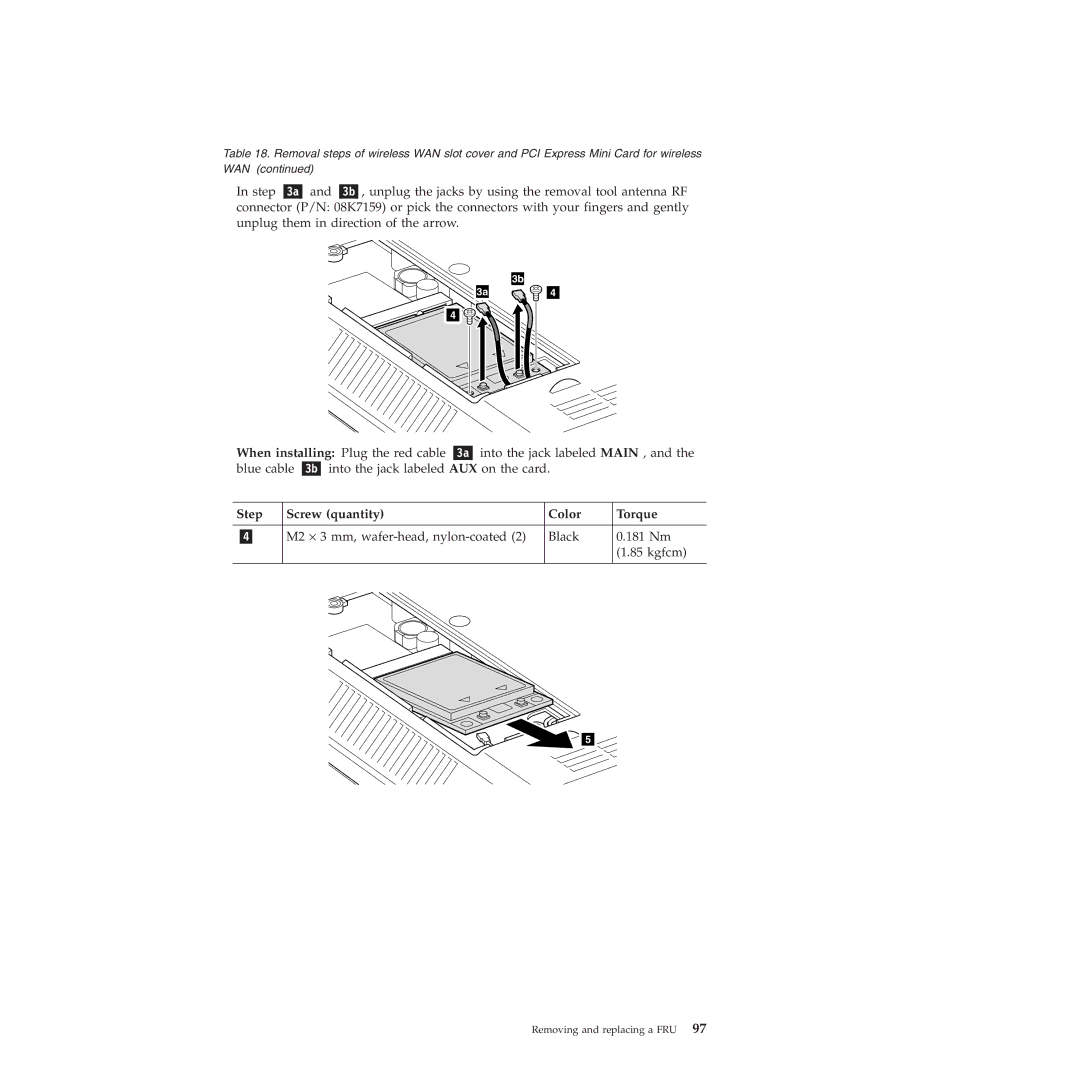
Table 18. Removal steps of wireless WAN slot cover and PCI Express Mini Card for wireless WAN (continued)
In step and , unplug the jacks by using the removal tool antenna RF connector (P/N: 08K7159) or pick the connectors with your fingers and gently unplug them in direction of the arrow.
| 3b |
3a | 4 |
![]() 4
4
When installing: Plug the red cable | into the jack labeled MAIN , and the | ||||
blue cable | into the jack labeled AUX on the card. |
| |||
|
|
|
|
| |
Step | Screw (quantity) |
| Color | Torque | |
|
|
|
| ||
| M2 ⋅ 3 mm, | Black | 0.181 Nm | ||
|
|
|
|
| (1.85 kgfcm) |
|
|
|
|
|
|
![]()
![]() 5
5![]()
Removing and replacing a FRU 97
