1190 Base cover assembly and DC-in connector cable
For access, remove these FRUs in order:
•“1010 Battery pack” on page 63
•“1020 ExpressCard blank bezel” on page 64
•“1030 Serial Ultrabay Enhanced device or travel bezel” on page 65
•“1040 Hard disk drive (HDD) and solid state drive (SSD)” on page 66
•“1050 DIMM slot cover” on page 69
•“1070 PCI Express Mini Card for wireless WAN” on page 71
•“1080 Keyboard” on page 73
•“1110 PCI Express Mini Card for wireless LAN” on page 81
•“1120 Keyboard bezel assembly, FPC cable, and Bluethooth daughter card” on page 83
•“1150 Speaker assembly” on page 91
•“1160 LCD unit” on page 93
•“1170 Fan assembly” on page 97
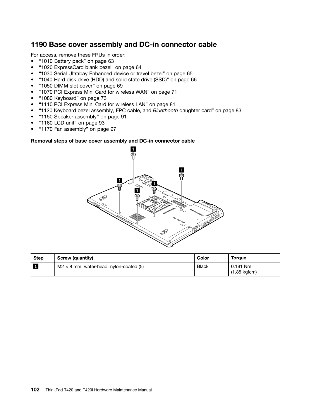
Removal steps of base cover assembly and
| Step | Screw (quantity) | Color | Torque | |
|
|
|
|
|
|
|
|
| M2 × 8 mm, | Black | 0.181 Nm |
| 1 |
| |||
|
|
|
|
| (1.85 kgfcm) |
|
|
|
|
|
|