2040 LCD panel and LCD cable
For access, remove these FRUs in order:
•“1010 Battery pack” on page 63
•“1020 ExpressCard blank bezel” on page 64
•“1050 DIMM slot cover” on page 69
•“1070 PCI Express Mini Card for wireless WAN” on page 71
•“1080 Keyboard” on page 73
•“1110 PCI Express Mini Card for wireless LAN” on page 81
•“1120 Keyboard bezel assembly, FPC cable, and Bluethooth daughter card” on page 83
•“1150 Speaker assembly” on page 91
•“1160 LCD unit” on page 93
•“2010 LCD bezel assembly” on page 112
•“2020 LED board” on page 113
•“2030 Integrated camera” on page 115
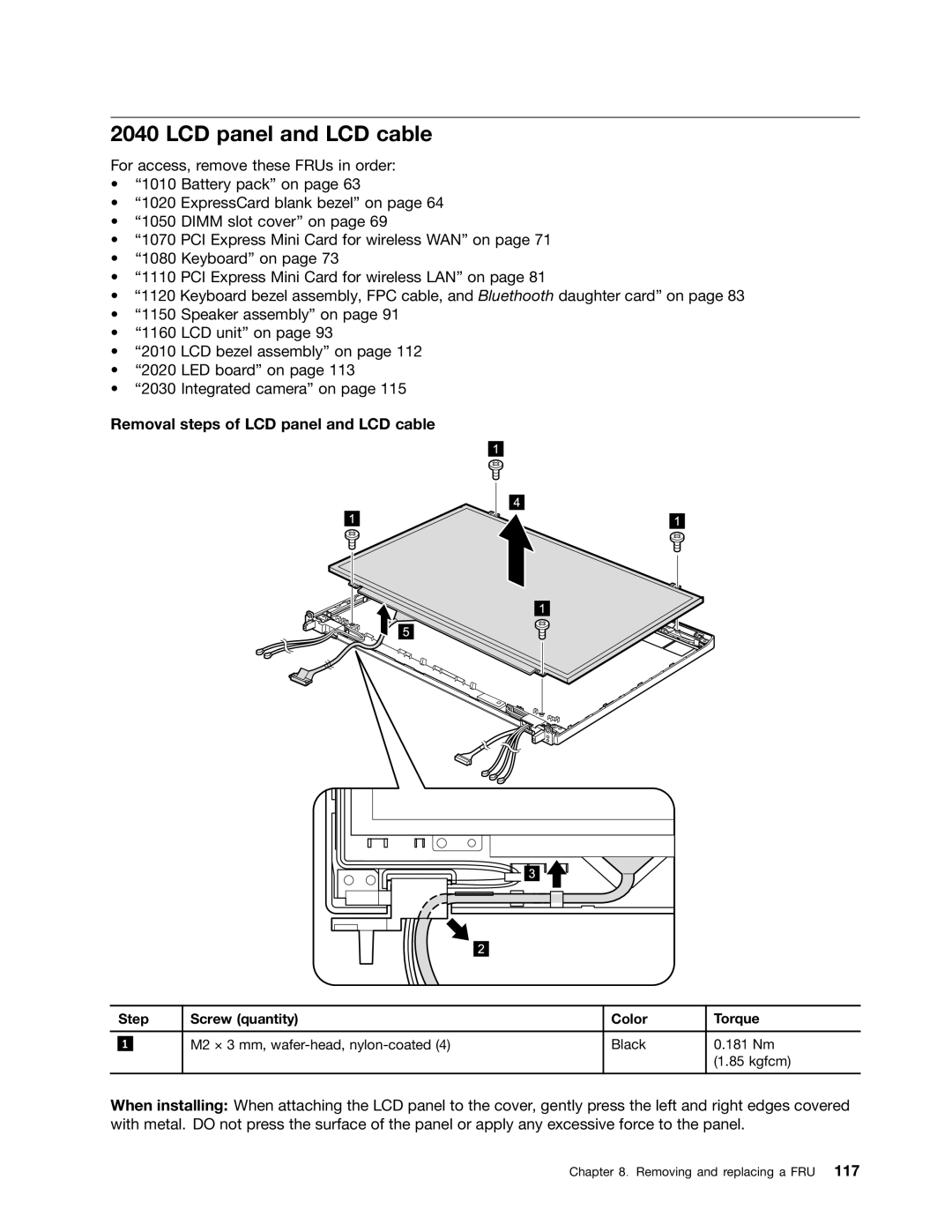
Removal steps of LCD panel and LCD cable
| Step | Screw (quantity) | Color | Torque | |
|
|
|
|
|
|
|
|
| M2 × 3 mm, | Black | 0.181 Nm |
| 1 |
| |||
|
|
|
|
| (1.85 kgfcm) |
|
|
|
|
|
|
When installing: When attaching the LCD panel to the cover, gently press the left and right edges covered with metal. DO not press the surface of the panel or apply any excessive force to the panel.