Installation
Lexicon
The Rear Panel
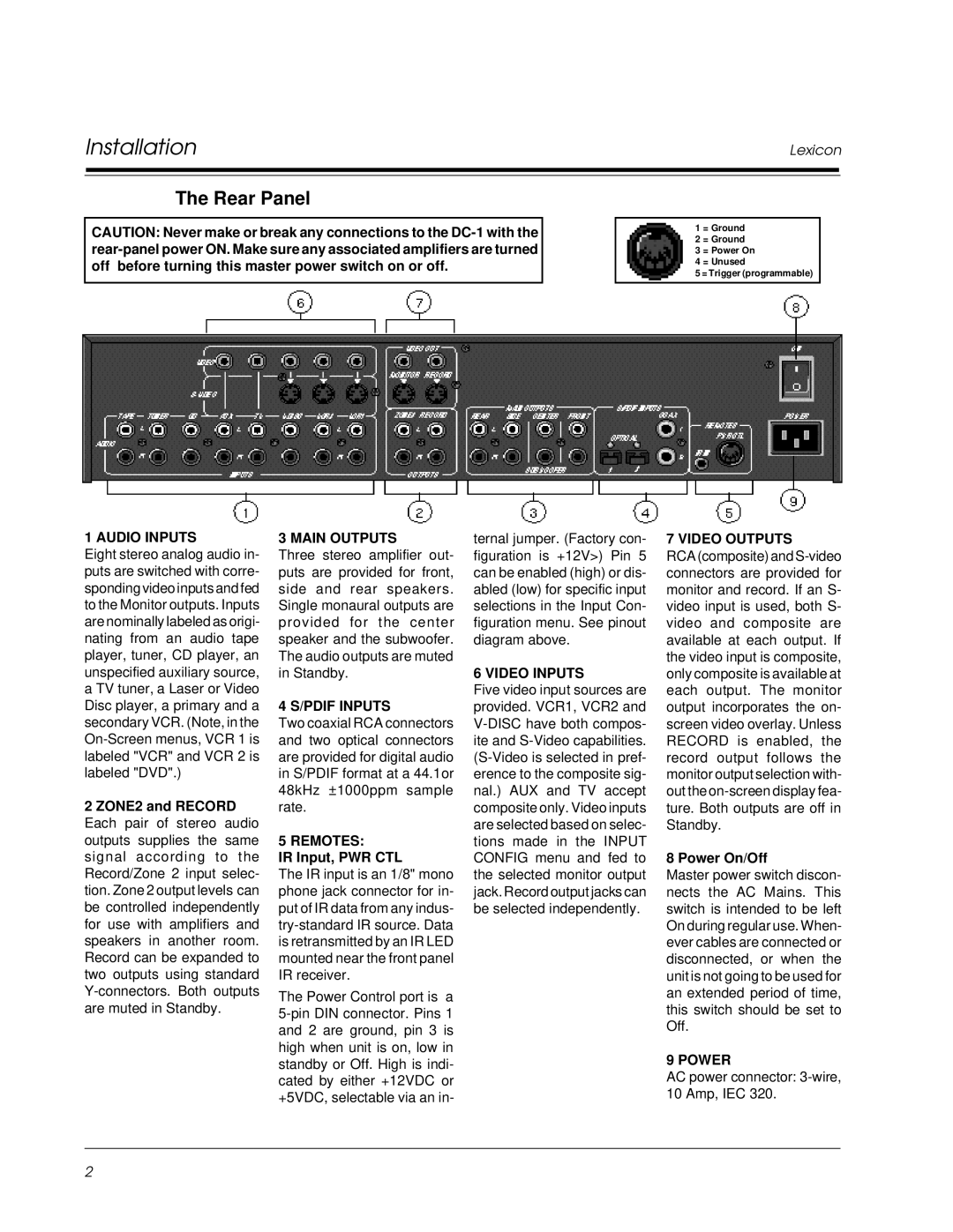
CAUTION: Never make or break any connections to the
1 = Ground
2 = Ground
3 = Power On
4 = Unused
5 = Trigger (programmable)
1 AUDIO INPUTS
Eight stereo analog audio in- puts are switched with corre- sponding video inputs and fed to the Monitor outputs. Inputs are nominally labeled as origi- nating from an audio tape player, tuner, CD player, an unspecified auxiliary source, a TV tuner, a Laser or Video Disc player, a primary and a secondary VCR. (Note, in the
2 ZONE2 and RECORD Each pair of stereo audio outputs supplies the same signal according to the Record/Zone 2 input selec- tion. Zone 2 output levels can be controlled independently for use with amplifiers and speakers in another room. Record can be expanded to two outputs using standard
3 MAIN OUTPUTS
Three stereo amplifier out- puts are provided for front, side and rear speakers. Single monaural outputs are provided for the center speaker and the subwoofer. The audio outputs are muted in Standby.
4 S/PDIF INPUTS
Two coaxial RCA connectors and two optical connectors are provided for digital audio in S/PDIF format at a 44.1or 48kHz ±1000ppm sample rate.
5 REMOTES:
IR Input, PWR CTL
The IR input is an 1/8" mono phone jack connector for in- put of IR data from any indus-
The Power Control port is a
ternal jumper. (Factory con- figuration is +12V>) Pin 5 can be enabled (high) or dis- abled (low) for specific input selections in the Input Con- figuration menu. See pinout diagram above.
6 VIDEO INPUTS
Five video input sources are provided. VCR1, VCR2 and
7 VIDEO OUTPUTS
RCA (composite) and
8 Power On/Off
Master power switch discon- nects the AC Mains. This switch is intended to be left On during regular use. When- ever cables are connected or disconnected, or when the unit is not going to be used for an extended period of time, this switch should be set to Off.
9 POWER
AC power connector:
2