Manuals
/
LG Electronics
/
Computer Equipment
/
Laptop
LG Electronics
LM50
service manual
Ch5. Removing and replacing a part
Models:
LM50
1
74
114
114
Download
114 pages
30.76 Kb
71
72
73
74
75
76
77
78
Specifications
Before replacing parts
Password
· Load Setup Defaults
Ch4. Symptom-to-part index
· Boot-time Diagnostic Screen
Power on Boot
Page 74
Image 74
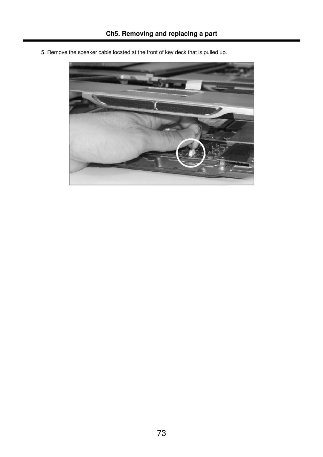
Ch5. Removing and replacing a part
5. Remove the speaker cable located at the front of key deck that is pulled up.
73
Page 73
Page 75
Page 74
Image 74
Page 73
Page 75
Contents
LM40/50 LG Electronics
Page
„ Strategy for replacing a hard-disk drive
Ch1. Service information
Before replacing parts
Ch1. Service information Safety notices
Ch1. Service information Safety information „ General safety
Ch1. Service information „ Electrical safety
Ch1. Service information
Ch1. Service information „ Safety inspection guide
„ Grounding requirements
Ch1. Service information Laser compliance statement
Backup Standby RTC battery safety information
Important Notes
Ch1. Service information Read this first
„ What to do first
Followings are not covered under warranty
Ch2. Locations
„ Front view
„ Right view 15/14.1
Ch2. Locations „ Rear view 15/14.1
„ Left view 15/14.1
Security key hole Kensington Lock
„ Specification
Ch3. System information
Ch3. System information „ Model Configuration
Ch3. System information „ System Block Diagram
Ch3. System information „ Fn key combinations
Ch3. System information „ Status indicators
Ch3. System information „ Bios Flash
Ch3. System information „ How to update flash ROM in Windows
Ch3. System information
Ch3. System information „ Bios Setup
Ch3. System information „ Default screen
Main, Advanced, Security, Boot, Exit
Ch3. System information „ Using the keys
Ch3. System information „ Main Menu
· TouchPad Support
Ch3. System information „ Advanced Menu
· Legacy USB Support
· Internal Keypad
· Parallel port modes
· Boot-time Diagnostic Screen
· Parallel Port
Ch3. System information „ Security Menu
· Setting a password
· Set Supervisor Password
Power on Boot
· Set User Password
Ch3. System information
· Password on boot
Ch3. System information
· Set HDD Password
Ch3. System information
· Changing or removing a password
· Removable Devices
Ch3. System information „ Boot Menu
· CD-ROM Drive
· Hard Drive
· Exit Saving Changes
· Load Setup Defaults
Ch3. System information „ Exit Menu
· Exit Discarding Changes
· Discard Changes
· Save Changes
Ch4. Symptom-to-part index
„ Power system checkout
Ch4. Symptom-to-part index
Ch4. Symptom-to-part index
Terminal Voltage V dc Ground
Ch4. Symptom-to-part index „ Numeric error codes
Symptom / Error FRU or action, in sequence
DMA test failed System board 02F6
02F7
Ch4. Symptom-to-part index „ Error message
Ch4. Symptom-to-part index „ LCD-related symptoms
Ch4. Symptom-to-part index „ Indeterminate problems
Removing and replacing a part FRU
Ch5. Removing and replacing a part
Ch5. Removing and replacing a part „ 1010 Battery Pack
Ch5. Removing and replacing a part „ 1020 Hard Disk Drive
Ch5. Removing and replacing a part „ 1030 Retainer
Ch5. Removing and replacing a part
Disconnect the keyboard connector
Ch5. Removing and replacing a part „ 1040 Retainer
Ch5. Removing and replacing a part „ 1050 Fan Assembly
Ch5. Removing and replacing a part
1SZZBZ4014A
1SZZBZ4014A
Ch5. Removing and replacing a part „ 1070 Wireless LAN Card
Ch5. Removing and replacing a part „ 1080 MDC Modem Card
Ch5. Removing and replacing a part „ 1090 Display Module
Remove two hinge cover screws FRU No Specification Qty
Ch5. Removing and replacing a part
Ch5. Removing and replacing a part
Ch5. Removing and replacing a part
Ch5. Removing and replacing a part „ 1100 Keyboard Deck
Ch5. Removing and replacing a part 14.1
Ch5. Removing and replacing a part
1SZZBZ4018B
Ch5. Removing and replacing a part
Ch5. Removing and replacing a part
Ch5. Removing and replacing a part „ 1110 Main Board
Ch5. Removing and replacing a part
Remove the S-Video connector Remove the LAN S/B connector
1SZZBA4014A
Hold M/B with your both hand and pull it up to remove
1SZZBA4017B
Ch5. Removing and replacing a part
Ch5. Removing and replacing a part „ 1130 S-Video Sub-Board
Ch5. Removing and replacing a part „ 1140 Display Module
Ch5. Removing and replacing a part
Ch5. Removing and replacing a part
1SZZBA4041A
Ch5. Removing and replacing a part
Remove LCD from the LCD rear panel
Part lists
Ch6. Part lists MKB21
Ch6. Part lists
LG P/N Specification Remarks MKC08
Mckinley N Sunrex Czech LM Refresh
Mckinley N OKI Thailand LM Refresh
LG P/N Specification Remarks MKC13
LG P/N Specification Remarks MKS01
LG P/N Specification Remarks MKM08
Case LCD
Case LCD
MKM22 MKL16 MKL06 MKL05 MKL04
TFT LCD, LG Philips LP150E06-A2 15.0 Inch SXGA+
100
101
102
Type Intel 4 Layers 1-14 Network Connection
103
104
105
Thermal PAD 11X11 MM on Northbridge
106
107
108
109
110
Mckinley N OKI Hungary LM Refresh
111
112
MEMORY, Hynix HYMD232M646C6-J Sodimm 256MB DDR 333MHZ
LG P/N Specification
113
Top
Page
Image
Contents