Ch5. Removing and replacing a part
Remove the following parts in order before replacing this part.
a. Battery Pack(1010) b. Keyboard(1030) c. Retainer(1040)
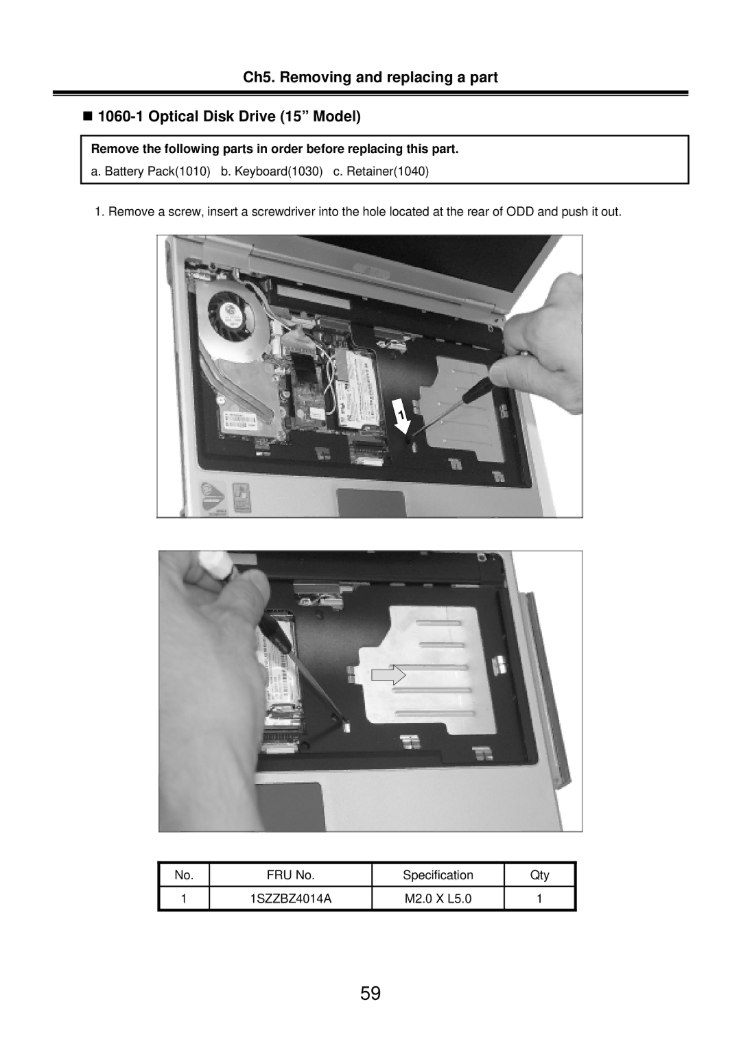
1. Remove a screw, insert a screwdriver into the hole located at the rear of ODD and push it out.
No. | FRU No. | Specification | Qty |
|
|
|
|
1 | 1SZZBZ4014A | M2.0 X L5.0 | 1 |
|
|
|
|
59