Chapter 1 - General Description | User Manual |
Network Power Switch
1.6 Potential free contacts
The Network Power Switch status can be checked with the
Table
Status |
| Termination available of 37 pin | ||||||
|
|
|
|
|
|
|
|
|
|
| NC |
| NO | Common | NC | NO | Common |
|
|
|
|
|
|
|
| |
Overload | 20 |
| 1 | 2 | 3 | 21 | 19 | |
|
|
|
|
|
|
|
| |
Priority | 23 |
| 4 | 5 | 6 | 24 | 19 | |
|
|
|
|
|
|
|
|
|
S1 | Feed | 7 |
| 25 | 26 | 27 | 8 | 19 |
|
|
|
|
|
|
|
|
|
S1 | Healthy | 28 |
| 9 | 10 | 11 | 29 | 19 |
|
|
|
|
|
|
|
|
|
S2 | Healthy | 12 |
| 30 | 31 | 32 | 13 | 19 |
|
|
|
|
|
|
|
|
|
S2 | Feed | 33 |
| 14 | 15 | 16 | 34 | 19 |
|
|
|
|
|
|
|
| |
Unsynch | 17 |
| 35 | 36 | 37 | 18 | 19 | |
|
|
|
|
|
|
|
|
|
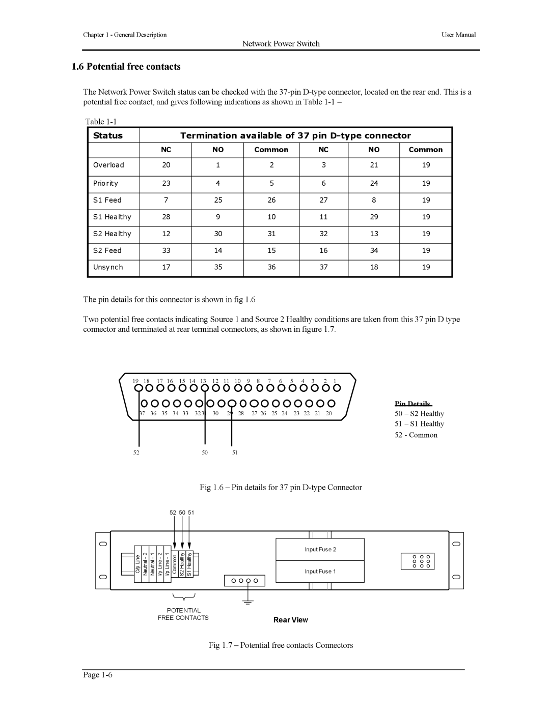
The pin details for this connector is shown in fig 1.6
Two potential free contacts indicating Source 1 and Source 2 Healthy conditions are taken from this 37 pin D type connector and terminated at rear terminal connectors, as shown in figure 1.7.
19 18 17 16 15 14 13 12 11 10 9 8 7 6 5 4 3 2 1
|
|
| Pin Details | |
37 36 35 34 33 | 32 31 30 | 29 28 27 26 25 24 23 22 21 20 | 50 | – S2 Healthy |
|
|
| 51 | – S1 Healthy |
|
|
| 52 | - Common |
52 | 50 | 51 |
|
|
Fig 1.6 – Pin details for 37 pin
52 50 51
S1 Healthy
S2 Healthy
Common
I/p Line - 1
I/p Line - 2
Neutral - 1
Neutral - 2
O/p Line
POTENTIAL
FREE CONTACTS
Input Fuse 2
Input Fuse 1
Rear View
Fig 1.7 – Potential free contacts Connectors
Page