User Manual | Chapter 2 – Operating Instructions |
Network Power Switch
2 Chapter 2 – Operating Instructions
2.1 Introduction
The Network Power Switch can be considered to be in one of the three operating conditions:
•Normal Operation - All relevant power switches and fuses closed and the Load is connected to Network Power Switch output
•Manual Bypass – The load is connected to the input supply directly.
•Shut down - All power switches are off and load is not operational.
2.2General Notes
NOTE: All users controls and indicators mentioned in these procedures are identified in chapter1
External Cable
O/p Line
Neutral - 2
Neutral - 1
I/p Line - 2
I/p Line - 1
Common
S2 Healthy
S1 Healthy![]()
![]()
Input Fuse 2
Input Fuse 1
Connector
External Cables Potential | Earthing | |
Free Contacts | ||
|
Rear View
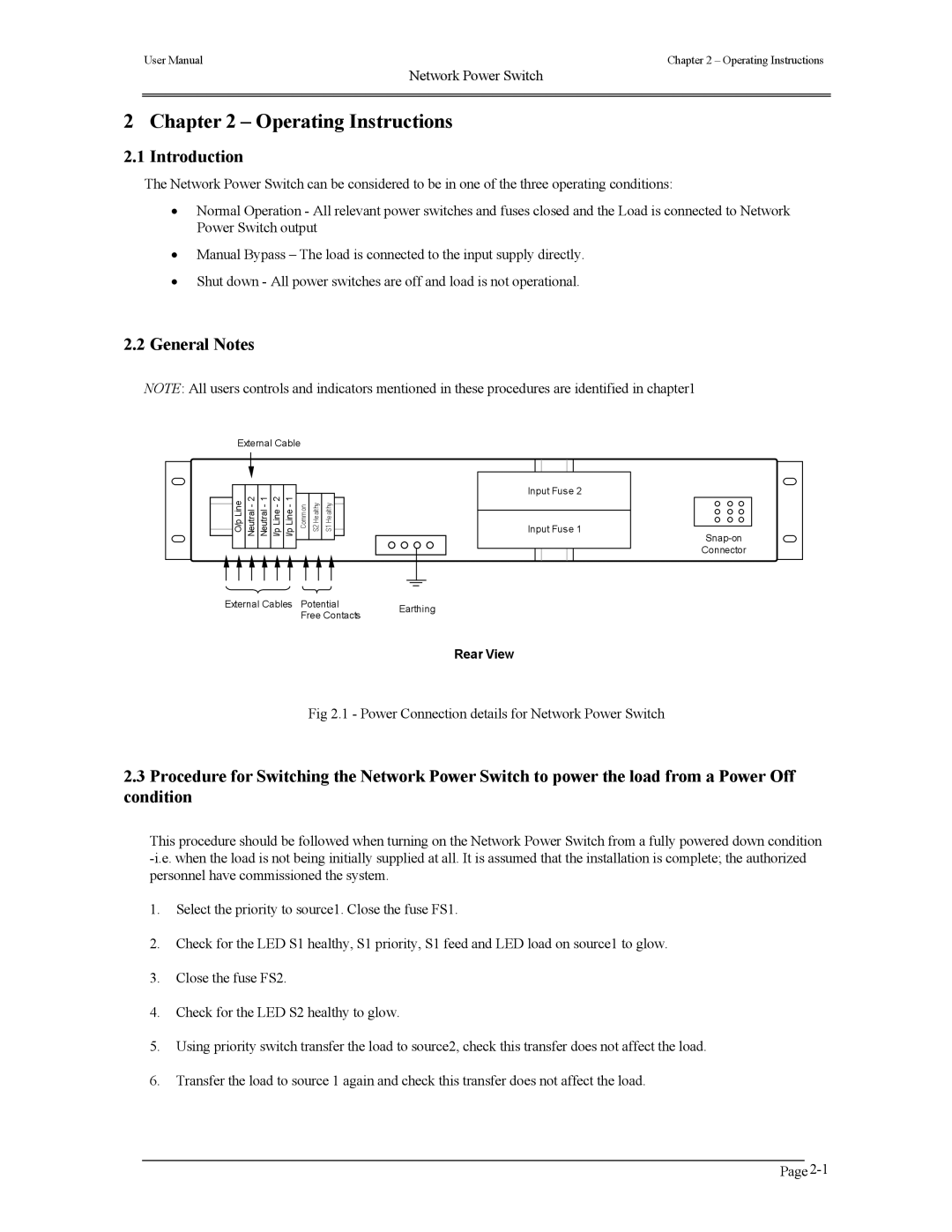
Fig 2.1 - Power Connection details for Network Power Switch
2.3Procedure for Switching the Network Power Switch to power the load from a Power Off condition
This procedure should be followed when turning on the Network Power Switch from a fully powered down condition
1.Select the priority to source1. Close the fuse FS1.
2.Check for the LED S1 healthy, S1 priority, S1 feed and LED load on source1 to glow.
3.Close the fuse FS2.
4.Check for the LED S2 healthy to glow.
5.Using priority switch transfer the load to source2, check this transfer does not affect the load.
6.Transfer the load to source 1 again and check this transfer does not affect the load.