User Manual | Chapter 1 - General Description |
Network Power Switch
1 Chapter 1 – General description
1.1 Introduction
The Network Power Switch is an automatic static transfer switch designed to provide fast automatic transfers between two independent, synchronous AC power sources to provide continuity of AC power to critical equipment, such as information technology equipment.
One of the two AC inputs is designed as the “preferred” source to which the Network Power Switch will connect the load as long as the designated input source is within the acceptable limits, the Network Power Switch is designed to transfer the output load to the “alternate “input source, as long as the alternate source is within the acceptable voltage limits.
The Network Power Switch provides fast,
The maximum sense and transfer times are within the tolerance of IEEE Standard 446 susceptibility curve for information technology equipment to allow uninterrupted load equipment operation.
In case of overload, Network Power Switch gives the alarm. Under
Manual Bypass Switch
The entire power static switch module is hot swappable. Before removing this module the load is transferred, without break to any one of the source directly by using the Manual bypass switch. After replacing the static switch module, the load is restored on static switch module, using the Manual bypass switch.
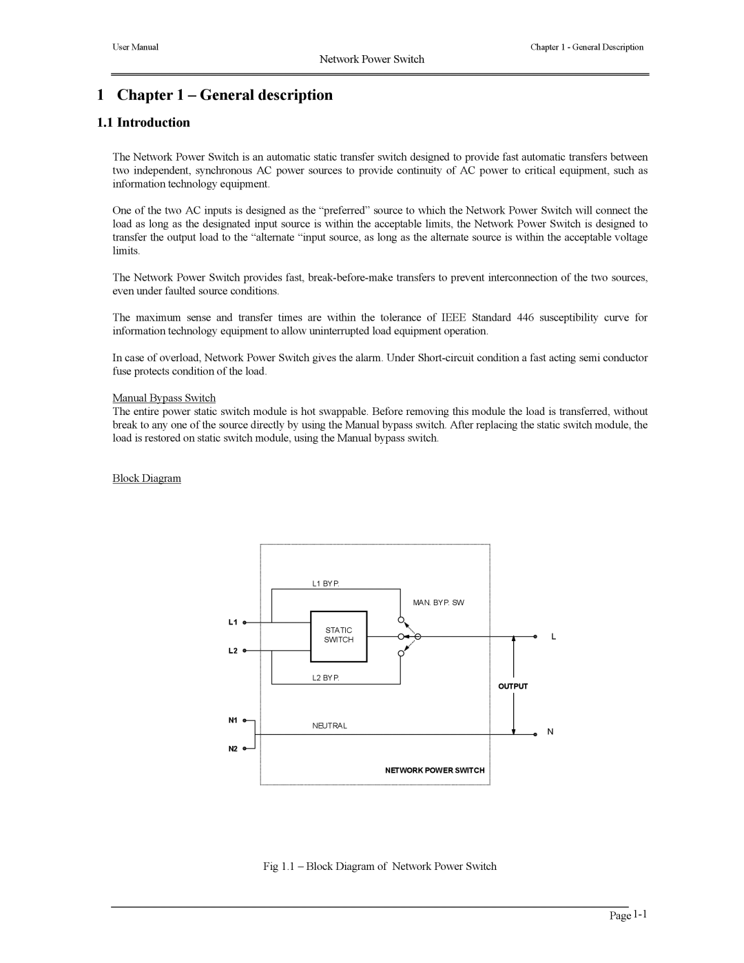
Block Diagram
L1
L2
N1
N2
L1 BYP.
STATIC
SWITCH
L2 BYP.
NEUTRAL
MAN. BYP. SW
L
OUTPUT
N
NETWORK POWER SWITCH
Fig 1.1 – Block Diagram of Network Power Switch