Chapter 1 - General Description | User Manual |
Network Power Switch
1.2 Design Concept
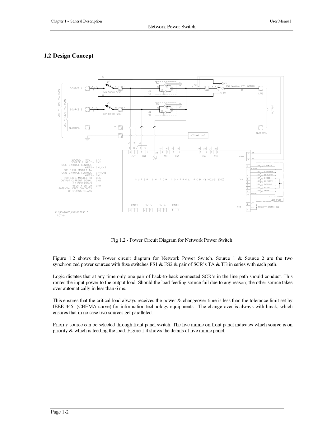
Fig 1.2 - Power Circuit Diagram for Network Power Switch
Figure 1.2 shows the Power circuit diagram for Network Power Switch. Source 1 & Source 2 are the two synchronized power sources with fuse switches FS1 & FS2 & pair of SCR’s TA & TB in series with each path.
Logic dictates that at any time only one pair of back-to-back connected SCR’s in the line path should conduct. This routes the input power to the output load. Should the load feeding source fail due to any reason; the other source takes over automatically in less than 6 ms.
This ensures that the critical load always receives the power & changeover time is less than the tolerance limit set by IEEE 446 (CBEMA curve) for information technology equipments. The change over is always with break, which ensures that in no case two sources get paralleled.
Priority source can be selected through front panel switch. The live mimic on front panel indicates which source is on priority & which is feeding the load. Figure 1.4 shows the details of live mimic panel.
Page