Procedure
1.Turn the
2.Set the module's baud rates and console port settings using the
3.Turn the
Communication Wiring
CMnet Wiring
NOTE: Only one
NOTE: The
1.Turn the
2.Check the network communication wiring for shorts and grounds.
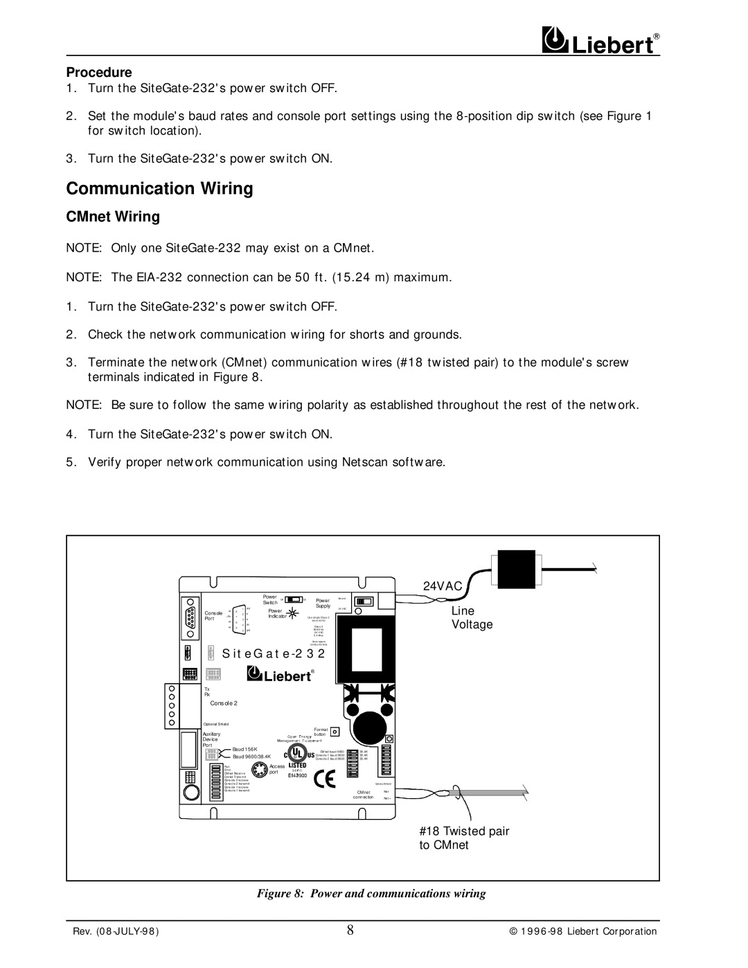
3.Terminate the network (CMnet) communication wires (#18 twisted pair) to the module's screw terminals indicated in Figure 8.
NOTE: Be sure to follow the same wiring polarity as established throughout the rest of the network.
4.Turn the
5.Verify proper network communication using Netscan software.
|
|
|
|
|
|
|
|
|
|
|
| Power |
|
|
|
| On | Power | Gro und |
|
|
|
|
| ||
|
|
|
|
|
|
|
|
|
|
|
|
|
| Off |
|
|
|
|
|
|
|
|
| |||
|
|
|
|
|
|
|
|
| 1 | dcd | Switch |
|
|
|
|
| Supply | 24 VAC |
|
|
|
|
| |||
|
|
|
|
|
|
|
|
|
| Power |
|
|
|
|
|
| ||||||||||
|
|
|
|
|
|
|
| n/c |
|
|
|
|
|
|
|
| ||||||||||
Console | 6 | xr |
|
|
|
|
|
|
|
|
| |||||||||||||||
+10v | 2 |
| Indicator |
| Us e sin gle Cl ass 2 |
|
|
|
|
|
| |||||||||||||||
Port |
| 7 | xt |
|
|
|
|
|
|
|
| |||||||||||||||
| n/c | 3 |
|
|
|
|
|
|
|
| sou rc eo nl y |
|
|
|
|
|
| |||||||||
|
|
|
|
|
|
|
| 8 | dtr |
|
|
|
|
|
|
|
|
|
|
|
|
|
|
| ||
|
|
|
|
|
|
|
| n/c | 4 |
|
|
|
|
|
|
|
| Cl as s 2 |
|
|
|
|
|
| ||
|
|
|
|
|
|
|
| 9 | gnd |
|
|
|
|
|
|
|
| 50 |
|
|
|
|
|
| ||
|
|
|
|
|
|
|
|
| 5 |
|
|
|
|
|
|
|
|
|
|
|
|
|
| |||
|
|
|
|
|
|
|
|
|
|
|
|
|
|
|
|
|
|
|
| 2 4 VAC |
|
|
|
|
|
|
|
|
|
|
|
|
|
|
|
|
|
|
|
|
|
|
|
|
|
| 0.4 Amp |
|
|
|
|
|
|
|
|
|
|
|
|
|
|
|
|
|
|
|
|
|
|
|
|
|
| Us e c opp er |
|
|
|
|
|
|
|
|
|
|
|
|
|
|
|
|
|
|
|
|
|
|
|
|
|
| co nd uc to r on ly |
|
|
|
|
|
|
|
|
|
|
|
|
|
|
|
|
|
|
|
| |||||||||||||
|
|
|
|
|
|
|
|
|
|
|
|
|
|
|
|
|
|
|
|
|
|
|
|
|
|
|
|
|
|
|
|
|
|
|
|
|
|
|
|
|
|
|
|
|
|
|
|
|
|
|
|
|
|
|
|
|
|
|
|
|
|
|
|
|
|
|
|
|
|
|
|
|
|
|
|
|
|
|
|
|
Tx |
|
|
|
|
|
|
|
|
|
|
|
|
|
|
|
|
|
|
|
| ||||||
Rx |
|
|
|
|
|
|
|
|
|
|
|
|
|
|
|
|
|
|
|
| ||||||
|
| Cons ole 2 |
|
|
|
|
|
|
|
|
|
|
|
|
|
|
|
|
| |||||||
Optional Shield |
|
|
|
|
|
|
|
|
|
|
|
|
|
|
|
|
|
| ||||||||
Auxiliary |
|
|
|
|
|
|
|
|
|
|
|
|
| Forma t |
|
|
|
|
|
| ||||||
|
|
|
|
|
|
|
|
|
|
|
|
| b utton |
|
|
|
|
|
| |||||||
Device |
|
|
|
|
|
|
|
|
|
|
|
|
|
|
|
|
|
|
|
| ||||||
Port |
|
| Baud 156K |
|
|
|
|
|
|
|
| CMnet baud 9600 |
|
| 38.4K |
|
| |||||||||
|
|
|
|
|
|
|
|
| Baud 9600/38.4K |
|
|
|
| Console 1 baud 9600 |
|
| 38.4K |
|
| |||||||
|
|
|
|
|
|
|
|
|
|
|
| Console 2 baud 9600 |
|
| 38.4K |
|
| |||||||||
|
|
|
|
|
|
|
| Run |
|
|
|
| Access |
|
|
|
|
|
|
|
| |||||
|
|
|
|
|
|
|
|
|
|
|
|
|
|
|
|
|
|
| ||||||||
|
|
|
|
|
|
|
| Error |
|
|
|
| port |
|
|
|
|
|
|
|
| |||||
|
|
|
|
|
|
|
| CMnet Receiv e |
|
|
|
|
|
|
|
|
|
|
| |||||||
|
|
|
|
|
|
|
|
|
|
|
|
|
|
|
|
|
| |||||||||
|
|
|
|
|
|
|
| Cmnet Trans mit |
|
|
|
|
|
|
|
|
|
|
|
|
|
|
|
|
| |
|
|
|
|
|
|
|
|
|
|
|
|
|
|
|
|
|
|
|
|
|
|
|
|
| ||
|
|
|
|
|
|
|
| Cons ole 2 recieve |
|
|
|
|
|
|
|
|
|
|
|
|
|
|
| |||
|
|
|
|
|
|
|
|
|
|
|
|
|
|
|
|
|
|
|
|
|
|
| ||||
|
|
|
|
|
|
|
| Console 2 transmit |
|
|
|
|
|
|
|
|
|
|
|
|
| Opti ona lShie ld | ||||
|
|
|
|
|
|
|
|
|
|
|
|
|
|
|
|
|
|
|
|
| ||||||
|
|
|
|
|
|
|
| Cons ole 1 recieve |
|
|
|
|
|
|
|
|
|
|
|
|
|
|
| |||
|
|
|
|
|
|
|
|
|
|
|
|
|
|
|
|
|
|
|
|
|
|
| ||||
|
|
|
|
|
|
|
| Console 1 transmit |
|
|
|
|
|
|
|
|
|
|
| CMne t |
| Net - | ||||
|
|
|
|
|
|
|
|
|
|
|
|
|
|
|
|
|
| |||||||||
|
|
|
|
|
|
|
|
|
|
|
|
|
|
|
|
|
|
|
|
|
| |||||
|
|
|
|
|
|
|
|
|
|
|
|
|
|
|
|
|
|
|
|
|
|
| co nn ec tion |
| Net + | |
|
|
|
|
|
|
|
|
|
|
|
|
|
|
|
|
|
|
|
|
|
|
| ||||
|
|
|
|
|
|
|
|
|
|
|
|
|
|
|
|
|
|
|
|
|
| |||||
24VAC
Line
Voltage
#18 Twisted pair to CMnet
Figure 8: Power and communications wiring
Rev. | 8 | © |