Liebert AC4 user manual Controller Board Overview, Controller board components

Models: AC4

1 88
Download 88 pages 50.7 Kb
Page 10
Image 10

Introduction

1.6Controller Board Overview

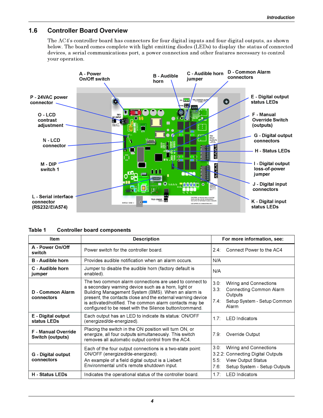
The AC4’s controller board has connectors for four digital inputs and four digital outputs, as shown below. The board comes complete with light emitting diodes (LEDs) to display the status of connected devices, a serial communications port, a power connection and other features necessary to control your operation.

A - Power

B - Audible

On/Off switch

horn


P - 24VAC power connector

C - Audible horn D - Common Alarm

jumper connectors

E - Digital output status LEDs

O - LCD

F - Manual

contrast

Override Switch

adjustment

(outputs)

N - LCD

G - Digital output

connectors

connector

H - Status LEDs


M - DIP

I - Digital output

switch 1

loss-of-power


jumper


J - Digital input


connectors

L - Serial interface

K - Digital input

connector

(RS232/EIA574)

status LEDs

Table 1

Controller board components


Item

Description

For more information, see:


A - Power On/Off

Power switch for the controller board.

2.4:

Connect Power to the AC4

switch


B - Audible horn

Provides audible notification when an alarm occurs.

N/A


C - Audible horn

Jumper to disable the audible horn (factory default is

N/A


jumper


enabled).


The two common alarm connections are used to connect to

3.0:

Wiring and Connections


a secondary warning device such as a horn, light or


3.3:

Connecting Common Alarm

D - Common Alarm

Building Management System (BMS). When an alarm is


Outputs

connectors

present, the contacts close and the external warning device


7.4:

Setup System - Setup Common


is activated/notified. The common alarm contacts may be


Alarm


configured to be reset with the Silence button/command.


E - Digital output

Each output has an LED to indicate its status: ON/OFF

1.7:

LED Indicators

status LEDs

(energized/de-energized).


F - Manual Override

Placing the switch in the ON position will turn ON, or


energize, all four outputs simultaneously. This switch

7.9:

Override Output

Switch (outputs)

removes all automatic output control from the AC4.


Each of the four output connections is a two-state point:

3.0:

Wiring and Connections

G - Digital output

ON/OFF (energized/de-energized).

3.2.2:

Connecting Digital Outputs

connectors

An example of a field digital output is a Liebert

5.5:

View Output Status


Environmental unit’s remote shutdown input.

7.6:

Setup System - Setup Outputs


H - Status LEDs

Indicates the operational status of the controller board.

1.7:

LED Indicators

4

Page 10
Image 10
Liebert AC4 user manual Controller Board Overview, Controller board components

AC4 specifications

The Liebert AC4 is a highly advanced cooling solution designed for critical environments, such as data centers and telecommunications facilities. As data demands rise and IT equipment generates significant heat, an effective cooling system is paramount to maintaining optimal performance and reliability. The Liebert AC4 stands out in this space, offering a blend of efficiency, flexibility, and innovative technology.

One of the main features of the Liebert AC4 is its adaptability to various configurations and applications. It can be deployed in both hot aisle and cold aisle containment setups, making it versatile for different data center designs. This flexibility allows facilities to implement cooling strategies that align perfectly with their specific layouts and operational requirements.

The Liebert AC4 employs cutting-edge, variable-speed fans that enhance energy efficiency. These fans adjust their speed according to the cooling load, ensuring that the system operates at peak efficiency while significantly reducing energy consumption. This feature is essential in critical environments, where minimizing operational costs is often as important as maintaining optimal temperatures.

In addition to energy-efficient cooling, the Liebert AC4 integrates advanced monitoring and control technologies. With built-in intelligence and compatibility with the Liebert SiteScan monitoring system, users can ensure real-time visibility into their cooling operations. This monitoring capability enables data center managers to make informed decisions and swiftly address any cooling anomalies, minimizing the risk of overheating and downtime.

Furthermore, the system is designed to be easy to install and maintain, reducing downtime during setup and upkeep. The modular design allows for scalability, enabling organizations to expand their cooling capabilities as their needs grow.

The Liebert AC4 also features a robust construction that enhances reliability and durability, making it an ideal choice for environments where equipment uptime is critical. Its streamlined design not only optimizes airflow and cooling distribution but also contributes to aesthetic considerations in professional settings.

In conclusion, the Liebert AC4 combines efficiency, versatility, and advanced technologies to deliver a reliable cooling solution for modern data centers and critical facilities. Its variable-speed fans, flexible configurations, and advanced monitoring capabilities position it as a leader in the competitive field of cooling solutions, ensuring that critical equipment remains operational and efficient. Organizations looking to enhance their cooling strategies will find the Liebert AC4 to be an invaluable asset in today’s fast-paced digital landscape.