Putting into operation
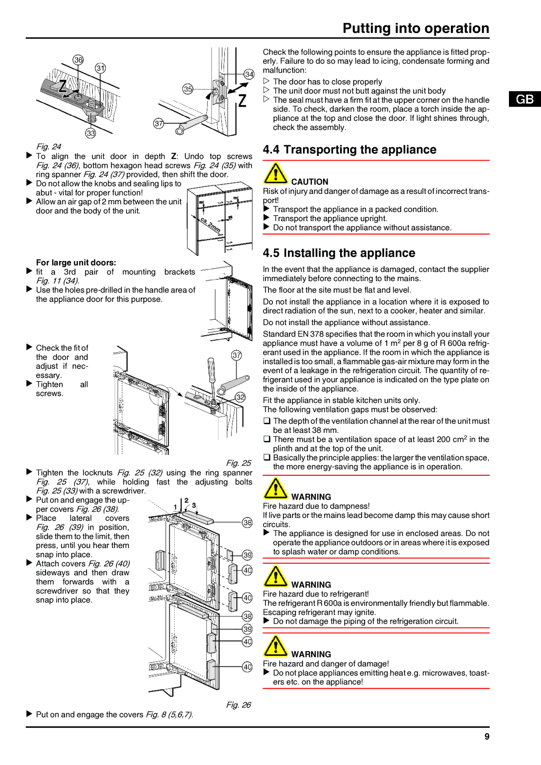
Fig. 24
u To align the unit door in depth Z: Undo top screws Fig. 24 (36), bottom hexagon head screws Fig. 24 (35) with ring spanner Fig. 24 (37) provided, then shift the door.
u Do not allow the knobs and sealing lips to abut - vital for proper function!
u Allow an air gap of 2 mm between the unit door and the body of the unit.
For large unit doors:
u fit a 3rd pair of mounting brackets Fig. 11 (34).
u Use the holes
u Check the fit of the door and adjust if nec- essary.
u Tighten all screws.
Fig. 25 u Tighten the locknuts Fig. 25 (32) using the ring spanner Fig. 25 (37), while holding fast the adjusting bolts
Fig. 25 (33) with a screwdriver. u Put on and engage the up-
per covers Fig. 26 (38).
u Place lateral covers Fig. 26 (39) in position, slide them to the limit, then press, until you hear them snap into place.
u Attach covers Fig. 26 (40) sideways and then draw them forwards with a screwdriver so that they snap into place.
Fig. 26
u Put on and engage the covers Fig. 8 (5,6,7).
Check the following points to ensure the appliance is fitted prop- erly. Failure to do so may lead to icing, condensate forming and malfunction:
wThe door has to close properly
wThe unit door must not butt against the unit body
wThe seal must have a firm fit at the upper corner on the handle side. To check, darken the room, place a torch inside the ap- pliance at the top and close the door. If light shines through, check the assembly.
4.4 Transporting the appliance
![]() CAUTION
CAUTION
Risk of injury and danger of damage as a result of incorrect trans- port!
u Transport the appliance in a packed condition. u Transport the appliance upright.
u Do not transport the appliance without assistance.
4.5 Installing the appliance
In the event that the appliance is damaged, contact the supplier immediately before connecting to the mains.
The floor at the site must be flat and level.
Do not install the appliance in a location where it is exposed to direct radiation of the sun, next to a cooker, heater and similar. Do not install the appliance without assistance.
Standard EN 378 specifies that the room in which you install your appliance must have a volume of 1 m2 per 8 g of R 600a refrig- erant used in the appliance. If the room in which the appliance is installed is too small, a flammable
Fit the appliance in stable kitchen units only. The following ventilation gaps must be observed:
qThe depth of the ventilation channel at the rear of the unit must be at least 38 mm.
qThere must be a ventilation space of at least 200 cm2 in the plinth and at the top of the unit.
qBasically the principle applies: the larger the ventilation space, the more
![]() WARNING
WARNING
Fire hazard due to dampness!
If live parts or the mains lead become damp this may cause short circuits.
u The appliance is designed for use in enclosed areas. Do not operate the appliance outdoors or in areas where it is exposed to splash water or damp conditions.
![]() WARNING
WARNING
Fire hazard due to refrigerant!
The refrigerant R 600a is environmentally friendly but flammable. Escaping refrigerant may ignite.
u Do not damage the piping of the refrigeration circuit.
![]() WARNING
WARNING
Fire hazard and danger of damage!
u Do not place appliances emitting heat e.g. microwaves, toast- ers etc. on the appliance!
9