8 |
27 |
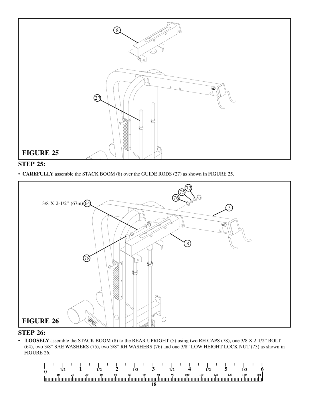
FIGURE 25 |
STEP 25: |
• CAREFULLY assemble the STACK BOOM (8) over the GUIDE RODS (27) as shown in FIGURE 25.
75 73 |
76 |
3/8 X |
5 |
8 |
78 |
FIGURE 26 |
STEP 26:
•LOOSELY assemble the STACK BOOM (8) to the REAR UPRIGHT (5) using two RH CAPS (78), one 3/8 X
|
|
|
|
|
|
|
|
|
|
|
|
|
|
|
|
|
|
|
|
|
|
|
|
|
|
|
|
|
|
|
0 | 1/2 |
| 1 | 1/2 | 2 | 1/2 | 3 |
| 1/2 | 4 |
| 1/2 | 5 |
| 1/2 | 6 | ||||||||||||||
10 |
| 20 | 30 | 40 | 50 | 60 |
| 70 |
| 80 | 90 | 100 |
| 110 |
|
| 120 |
| 130 | 140 | 150 |
| ||||||||
|
|
|
|
|
|
|
|
| ||||||||||||||||||||||
18