13 |
|
|
73 |
|
|
1 |
|
|
78 | 76 |
|
75 |
| |
53 3/8 X 4” | (97m) | |
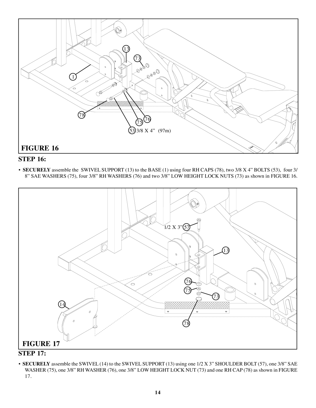
FIGURE 16 |
|
|
STEP 16: |
|
|
•SECURELY assemble the SWIVEL SUPPORT (13) to the BASE (1) using four RH CAPS (78), two 3/8 X 4” BOLTS (53), four 3/ 8” SAE WASHERS (75), four 3/8” RH WASHERS (76) and two 3/8” LOW HEIGHT LOCK NUTS (73) as shown in FIGURE 16.
1/2 X 3” 57 |
13 |
76 |
75 |
73 |
14 |
78 |
FIGURE 17 |
STEP 17: |
•SECURELY assemble the SWIVEL (14) to the SWIVEL SUPPORT (13) using one 1/2 X 3” SHOULDER BOLT (57), one 3/8” SAE WASHER (75), one 3/8” RH WASHER (76), one 3/8” LOW HEIGHT LOCK NUT (73) and one RH CAP (78) as shown in FIGURE 17.
14