Fresh Air Supply System
The fresh air supply ductwork from the HRV/ERV may be directly connected to the return air duct of the forced air system. Check the air flow balance of the HRV/ERV with the air handler blower both “ON” and “OFF” to determine that it does not imbalance the HRV/ERV more than 10%. Also, it is advisable to include a short length of flex duct or other
It may be necessary to install a separate fresh air supply ductwork system if the heating is other than forced air.
When installing an HRV/ERV, the designer and installer should be aware of local codes that may require smoke detectors and/or firestats in the HVAC or HRV/ERV ductwork.
Because an HRV/ERV is designed to bring fresh air into the building, structures may require supply voltage interrupt when smoke or flame sensors are triggered, or when a central fire alarm system is activated.
Supply air grilles may be ceiling or high wall mounted. Avoid locating incoming fresh air grilles that could cause a direct draft on the occupants as the incoming air may be below room temperature. A reheat duct heater can be installed to improve occupant comfort.
The use of balancing dampers or adjustable grilles to balance the flow rates into various rooms is recommended.
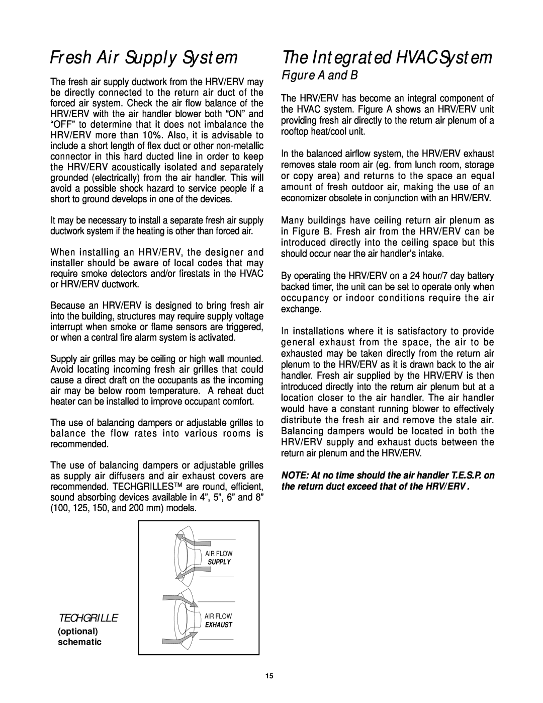
The use of balancing dampers or adjustable grilles as supply air diffusers and air exhaust covers are recommended. TECHGRILLES™ are round, efficient, sound absorbing devices available in 4”, 5”, 6” and 8” (100, 125, 150, and 200 mm) models.
The Integrated HVAC System
Figure A and B
The HRV/ERV has become an integral component of the HVAC system. Figure A shows an HRV/ERV unit providing fresh air directly to the return air plenum of a rooftop heat/cool unit.
In the balanced airflow system, the HRV/ERV exhaust removes stale room air (eg. from lunch room, storage or copy area) and returns to the space an equal amount of fresh outdoor air, making the use of an economizer obsolete in conjunction with an HRV/ERV.
Many buildings have ceiling return air plenum as in Figure B. Fresh air from the HRV/ERV can be introduced directly into the ceiling space but this should occur near the air handler’s intake.
By operating the HRV/ERV on a 24 hour/7 day battery backed timer, the unit can be set to operate only when occupancy or indoor conditions require the air exchange.
In installations where it is satisfactory to provide general exhaust from the space, the air to be exhausted may be taken directly from the return air plenum to the HRV/ERV as it is drawn back to the air handler. Fresh air supplied by the HRV/ERV is then introduced directly into the return air plenum but at a location closer to the air handler. The air handler would have a constant running blower to effectively distribute the fresh air and remove the stale air. Balancing dampers would be located in both the HRV/ERV supply and exhaust ducts between the return air plenum and the HRV/ERV.
NOTE: At no time should the air handler T.E.S.P. on the return duct exceed that of the HRV/ERV .
TECHGRILLE
(optional) schematic
AIR FLOW
SUPPLY
AIR FLOW
EXHAUST
15