Electrical Connections
It is recommended that a licensed electrician make all electrical connections. It is very important that the unit be properly grounded. It is recommended that a separate 15 amp/120 volt circuit be used.
WARNING: In order to prevent electric shock when cleaning or servicing the HRV/ERV, it is extremely important to confirm the polarity of the power line that is switched by the safety (disconnect) switch whose control arm is located on the outside of the electrical control box area. The hot line (black) is the proper line to be switched. To confirm the proper polarity, use a voltmeter or test lamp to make sure there is no power after the switch when the door is open. Check between that point and ground (on the cabinet). This must be done as occasionally some buildings are improperly wired. Always make sure the HRV/ERV is properly grounded.
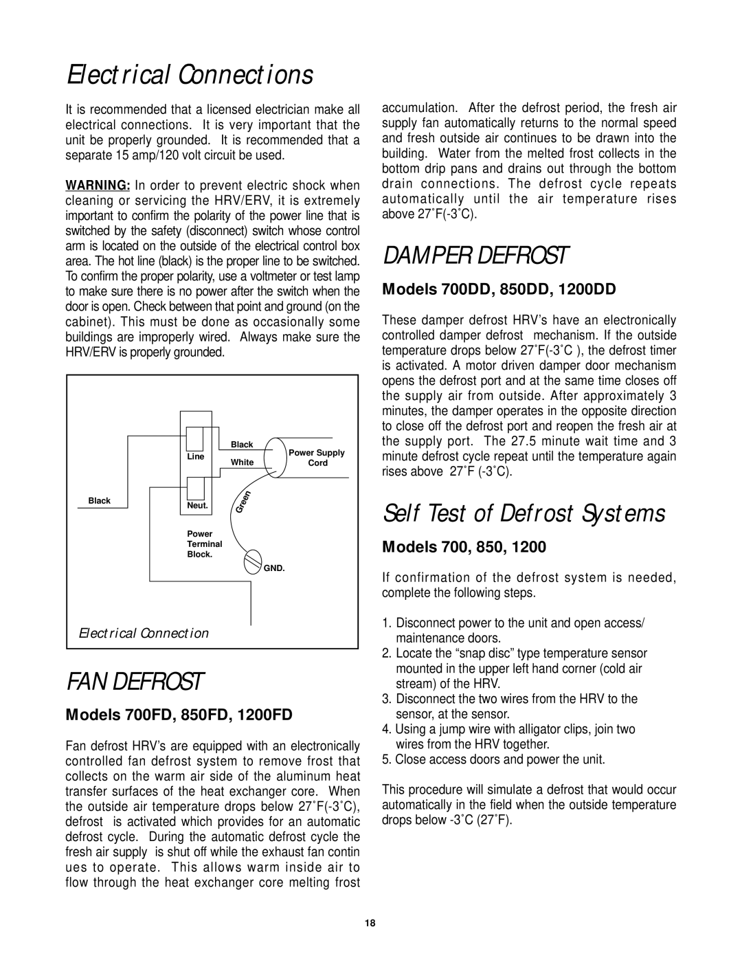
| Black | Power Supply |
| Line | |
| Cord | |
| White | |
Black | Neut. |
|
|
| |
| Power |
|
| Terminal |
|
| Block. |
|
|
| GND. |
Electrical Connection |
| |
FAN DEFROST
Models 700FD, 850FD, 1200FD
Fan defrost HRV’s are equipped with an electronically controlled fan defrost system to remove frost that collects on the warm air side of the aluminum heat transfer surfaces of the heat exchanger core. When the outside air temperature drops below
accumulation. After the defrost period, the fresh air supply fan automatically returns to the normal speed and fresh outside air continues to be drawn into the building. Water from the melted frost collects in the bottom drip pans and drains out through the bottom drain connections. The defrost cycle repeats automatically until the air temperature rises above
DAMPER DEFROST
Models 700DD, 850DD, 1200DD
These damper defrost HRV’s have an electronically controlled damper defrost mechanism. If the outside temperature drops below
Self Test of Defrost Systems
Models 700, 850, 1200
If confirmation of the defrost system is needed, complete the following steps.
1.Disconnect power to the unit and open access/ maintenance doors.
2.Locate the “snap disc” type temperature sensor mounted in the upper left hand corner (cold air stream) of the HRV.
3.Disconnect the two wires from the HRV to the sensor, at the sensor.
4.Using a jump wire with alligator clips, join two wires from the HRV together.
5.Close access doors and power the unit.
This procedure will simulate a defrost that would occur automatically in the field when the outside temperature drops below
18