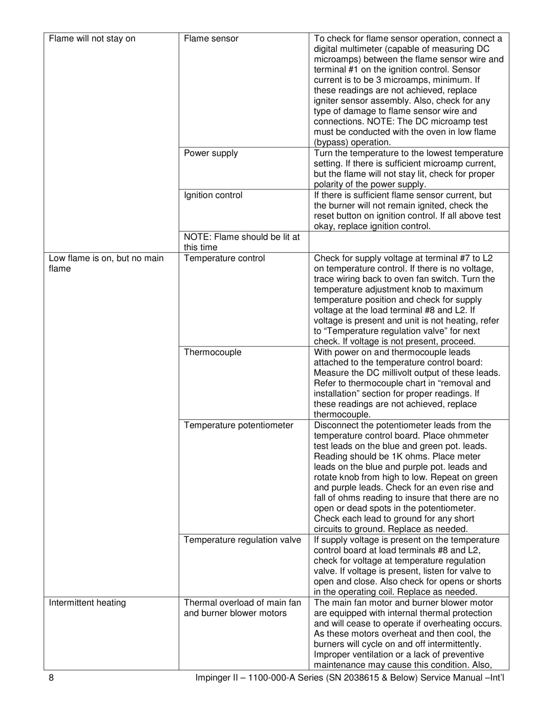
Flame will not stay on | Flame sensor | To check for flame sensor operation, connect a |
|
| digital multimeter (capable of measuring DC |
|
| microamps) between the flame sensor wire and |
|
| terminal #1 on the ignition control. Sensor |
|
| current is to be 3 microamps, minimum. If |
|
| these readings are not achieved, replace |
|
| igniter sensor assembly. Also, check for any |
|
| type of damage to flame sensor wire and |
|
| connections. NOTE: The DC microamp test |
|
| must be conducted with the oven in low flame |
|
| (bypass) operation. |
| Power supply | Turn the temperature to the lowest temperature |
|
| setting. If there is sufficient microamp current, |
|
| but the flame will not stay lit, check for proper |
|
| polarity of the power supply. |
| Ignition control | If there is sufficient flame sensor current, but |
|
| the burner will not remain ignited, check the |
|
| reset button on ignition control. If all above test |
|
| okay, replace ignition control. |
| NOTE: Flame should be lit at |
|
| this time |
|
Low flame is on, but no main | Temperature control | Check for supply voltage at terminal #7 to L2 |
flame |
| on temperature control. If there is no voltage, |
|
| trace wiring back to oven fan switch. Turn the |
|
| temperature adjustment knob to maximum |
|
| temperature position and check for supply |
|
| voltage at the load terminal #8 and L2. If |
|
| voltage is present and unit is not heating, refer |
|
| to “Temperature regulation valve” for next |
|
| check. If voltage is not present, proceed. |
| Thermocouple | With power on and thermocouple leads |
|
| attached to the temperature control board: |
|
| Measure the DC millivolt output of these leads. |
|
| Refer to thermocouple chart in “removal and |
|
| installation” section for proper readings. If |
|
| these readings are not achieved, replace |
|
| thermocouple. |
| Temperature potentiometer | Disconnect the potentiometer leads from the |
|
| temperature control board. Place ohmmeter |
|
| test leads on the blue and green pot. leads. |
|
| Reading should be 1K ohms. Place meter |
|
| leads on the blue and purple pot. leads and |
|
| rotate knob from high to low. Repeat on green |
|
| and purple leads. Check for an even rise and |
|
| fall of ohms reading to insure that there are no |
|
| open or dead spots in the potentiometer. |
|
| Check each lead to ground for any short |
|
| circuits to ground. Replace as needed. |
| Temperature regulation valve | If supply voltage is present on the temperature |
|
| control board at load terminals #8 and L2, |
|
| check for voltage at temperature regulation |
|
| valve. If voltage is present, listen for valve to |
|
| open and close. Also check for opens or shorts |
|
| in the operating coil. Replace as needed. |
Intermittent heating | Thermal overload of main fan | The main fan motor and burner blower motor |
| and burner blower motors | are equipped with internal thermal protection |
|
| and will cease to operate if overheating occurs. |
|
| As these motors overheat and then cool, the |
|
| burners will cycle on and off intermittently. |
|
| Improper ventilation or a lack of preventive |
|
| maintenance may cause this condition. Also, |
8 | Impinger II – | |