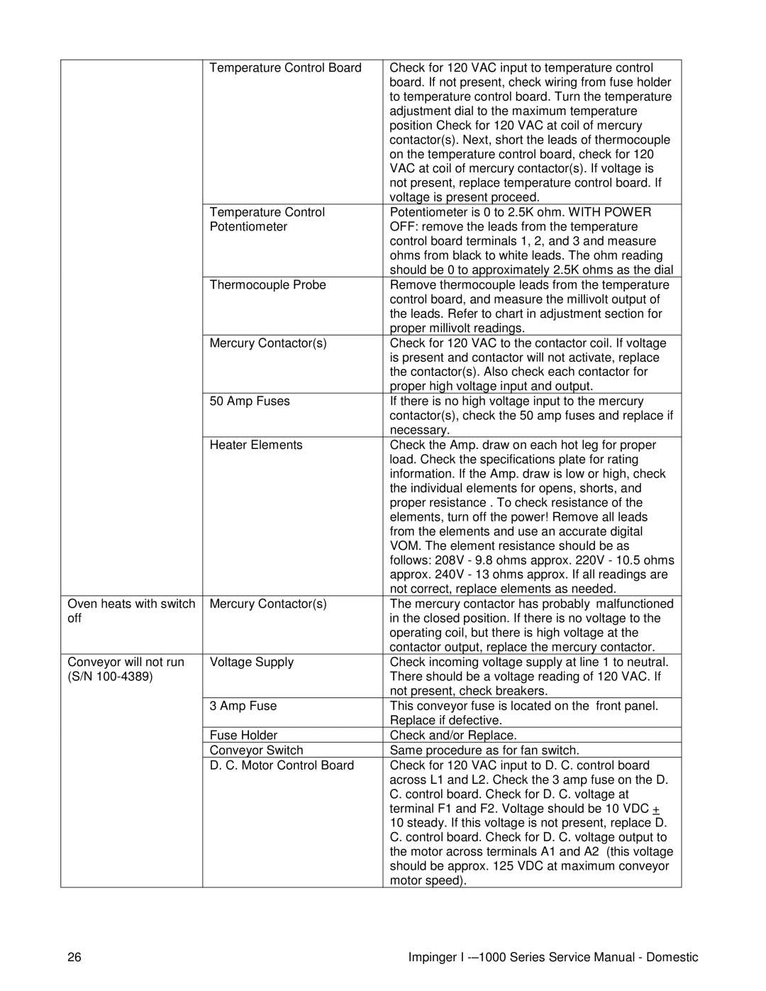
Temperature Control Board

Check for 120 VAC input to temperature control


board. If not present, check wiring from fuse holder


to temperature control board. Turn the temperature


adjustment dial to the maximum temperature


position Check for 120 VAC at coil of mercury


contactor(s). Next, short the leads of thermocouple


on the temperature control board, check for 120


VAC at coil of mercury contactor(s). If voltage is


not present, replace temperature control board. If


voltage is present proceed.


Temperature Control

Potentiometer is 0 to 2.5K ohm. WITH POWER


Potentiometer

OFF: remove the leads from the temperature


control board terminals 1, 2, and 3 and measure


ohms from black to white leads. The ohm reading


should be 0 to approximately 2.5K ohms as the dial


Thermocouple Probe

Remove thermocouple leads from the temperature


control board, and measure the millivolt output of


the leads. Refer to chart in adjustment section for


proper millivolt readings.


Mercury Contactor(s)

Check for 120 VAC to the contactor coil. If voltage


is present and contactor will not activate, replace


the contactor(s). Also check each contactor for


proper high voltage input and output.


50 Amp Fuses

If there is no high voltage input to the mercury


contactor(s), check the 50 amp fuses and replace if


necessary.


Heater Elements

Check the Amp. draw on each hot leg for proper


load. Check the specifications plate for rating


information. If the Amp. draw is low or high, check


the individual elements for opens, shorts, and


proper resistance . To check resistance of the


elements, turn off the power! Remove all leads


from the elements and use an accurate digital


VOM. The element resistance should be as


follows: 208V - 9.8 ohms approx. 220V - 10.5 ohms


approx. 240V - 13 ohms approx. If all readings are


not correct, replace elements as needed.

Oven heats with switch

Mercury Contactor(s)

The mercury contactor has probably malfunctioned

off


in the closed position. If there is no voltage to the


operating coil, but there is high voltage at the


contactor output, replace the mercury contactor.

Conveyor will not run

Voltage Supply

Check incoming voltage supply at line 1 to neutral.

(S/N 100-4389)


There should be a voltage reading of 120 VAC. If


not present, check breakers.


3 Amp Fuse

This conveyor fuse is located on the front panel.


Replace if defective.


Fuse Holder

Check and/or Replace.


Conveyor Switch

Same procedure as for fan switch.


D. C. Motor Control Board

Check for 120 VAC input to D. C. control board


across L1 and L2. Check the 3 amp fuse on the D.


C. control board. Check for D. C. voltage at


terminal F1 and F2. Voltage should be 10 VDC +


10 steady. If this voltage is not present, replace D.


C. control board. Check for D. C. voltage output to


the motor across terminals A1 and A2 (this voltage


should be approx. 125 VDC at maximum conveyor


motor speed).

26

Impinger I -–1000 Series Service Manual - Domestic

Page 26
Image 26
Lincoln 1000, 1400, 1200 service manual

1000, 1200, 1400 specifications

The Lincoln series, particularly the models Lincoln 1000, 1200, and 1400, represents an evolution in luxury vehicles, combining elegance with cutting-edge technology. Each model builds upon its predecessor while introducing features that enhance performance, comfort, and safety.

Starting with the Lincoln 1000, this model set the foundation for the series. It showcased a refined design characterized by sleek lines and an impressive presence on the road. The Lincoln 1000 was equipped with a powerful engine, delivering smooth acceleration and a quiet ride. Interior features included premium materials such as leather upholstery, real wood accents, and a state-of-the-art sound system. Additionally, it offered advanced climate control systems, ensuring passenger comfort. Safety features were also prioritized, with multiple airbags and stability control systems included to enhance driver confidence.

Moving on to the Lincoln 1200, this model took luxury to the next level. The exterior design was more aggressive, with a revised grille and enhanced aerodynamics for better fuel efficiency. The engine options expanded, offering hybrid technology for environmentally conscious consumers without sacrificing power. Inside, the Lincoln 1200 featured an upgraded infotainment system, incorporating a larger touchscreen display along with smartphone integration for connectivity on the go. This model also introduced adaptive cruise control and lane-keeping assist, showcasing Lincoln’s commitment to safety and innovation.

The Lincoln 1400 represents the pinnacle of this series. This model incorporates all the advancements of the previous iterations while introducing next-generation technologies. A hybrid powertrain with electric capabilities provides a quieter, more efficient drive. The design includes sophisticated lighting technology, such as adaptive LED headlights that adjust to road conditions. Inside, the cabin has been transformed into a haven of luxury, with customizable ambient lighting, heated and ventilated seats, and an advanced noise cancellation system for a serene driving experience. Furthermore, the Lincoln 1400 emphasizes driver assistance technology, featuring an array of sensors and cameras to support features like automatic parking and enhanced collision prevention systems.

In conclusion, the Lincoln 1000, 1200, and 1400 models showcase a remarkable journey of luxury and technology, with each iteration bringing forth innovative features and design enhancements that elevate the driving experience. As Lincoln continues to evolve, the commitment to craftsmanship, comfort, and cutting-edge technology remains central to its identity.