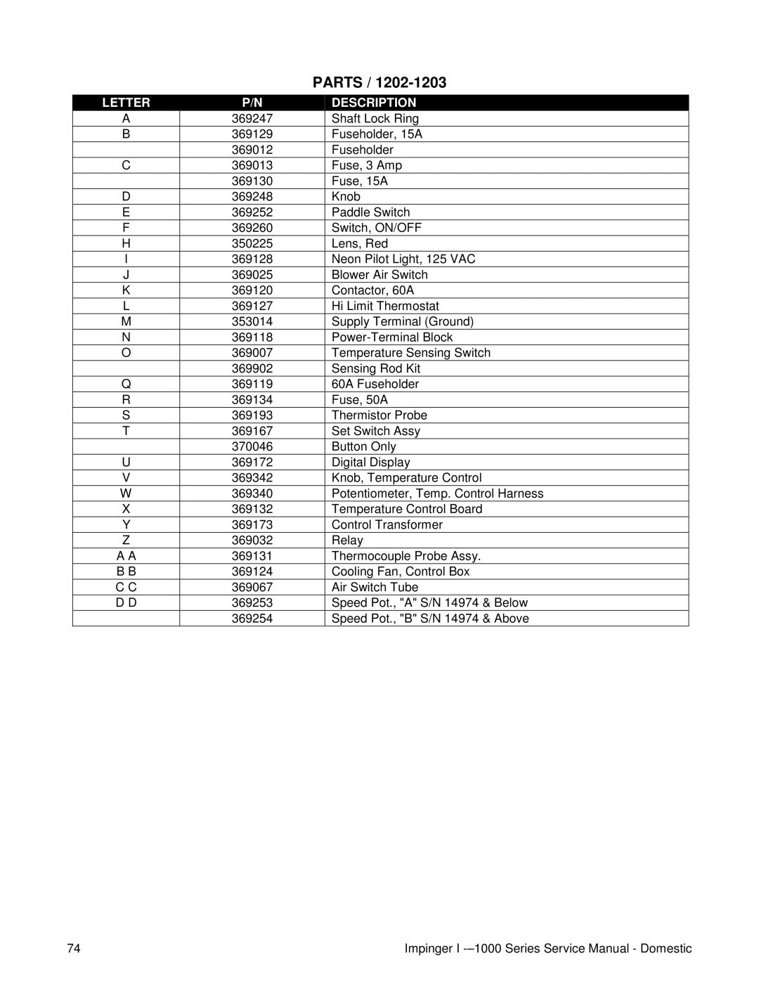
1000, 1200, 1400 specifications
The Lincoln series, particularly the models Lincoln 1000, 1200, and 1400, represents an evolution in luxury vehicles, combining elegance with cutting-edge technology. Each model builds upon its predecessor while introducing features that enhance performance, comfort, and safety.Starting with the Lincoln 1000, this model set the foundation for the series. It showcased a refined design characterized by sleek lines and an impressive presence on the road. The Lincoln 1000 was equipped with a powerful engine, delivering smooth acceleration and a quiet ride. Interior features included premium materials such as leather upholstery, real wood accents, and a state-of-the-art sound system. Additionally, it offered advanced climate control systems, ensuring passenger comfort. Safety features were also prioritized, with multiple airbags and stability control systems included to enhance driver confidence.
Moving on to the Lincoln 1200, this model took luxury to the next level. The exterior design was more aggressive, with a revised grille and enhanced aerodynamics for better fuel efficiency. The engine options expanded, offering hybrid technology for environmentally conscious consumers without sacrificing power. Inside, the Lincoln 1200 featured an upgraded infotainment system, incorporating a larger touchscreen display along with smartphone integration for connectivity on the go. This model also introduced adaptive cruise control and lane-keeping assist, showcasing Lincoln’s commitment to safety and innovation.
The Lincoln 1400 represents the pinnacle of this series. This model incorporates all the advancements of the previous iterations while introducing next-generation technologies. A hybrid powertrain with electric capabilities provides a quieter, more efficient drive. The design includes sophisticated lighting technology, such as adaptive LED headlights that adjust to road conditions. Inside, the cabin has been transformed into a haven of luxury, with customizable ambient lighting, heated and ventilated seats, and an advanced noise cancellation system for a serene driving experience. Furthermore, the Lincoln 1400 emphasizes driver assistance technology, featuring an array of sensors and cameras to support features like automatic parking and enhanced collision prevention systems.
In conclusion, the Lincoln 1000, 1200, and 1400 models showcase a remarkable journey of luxury and technology, with each iteration bringing forth innovative features and design enhancements that elevate the driving experience. As Lincoln continues to evolve, the commitment to craftsmanship, comfort, and cutting-edge technology remains central to its identity.
