OPERATION |
|
| |||
FEEDING WIRE ELECTRODE |
| Aluminum wires |
|
| between 1 and 3 |
WARNING |
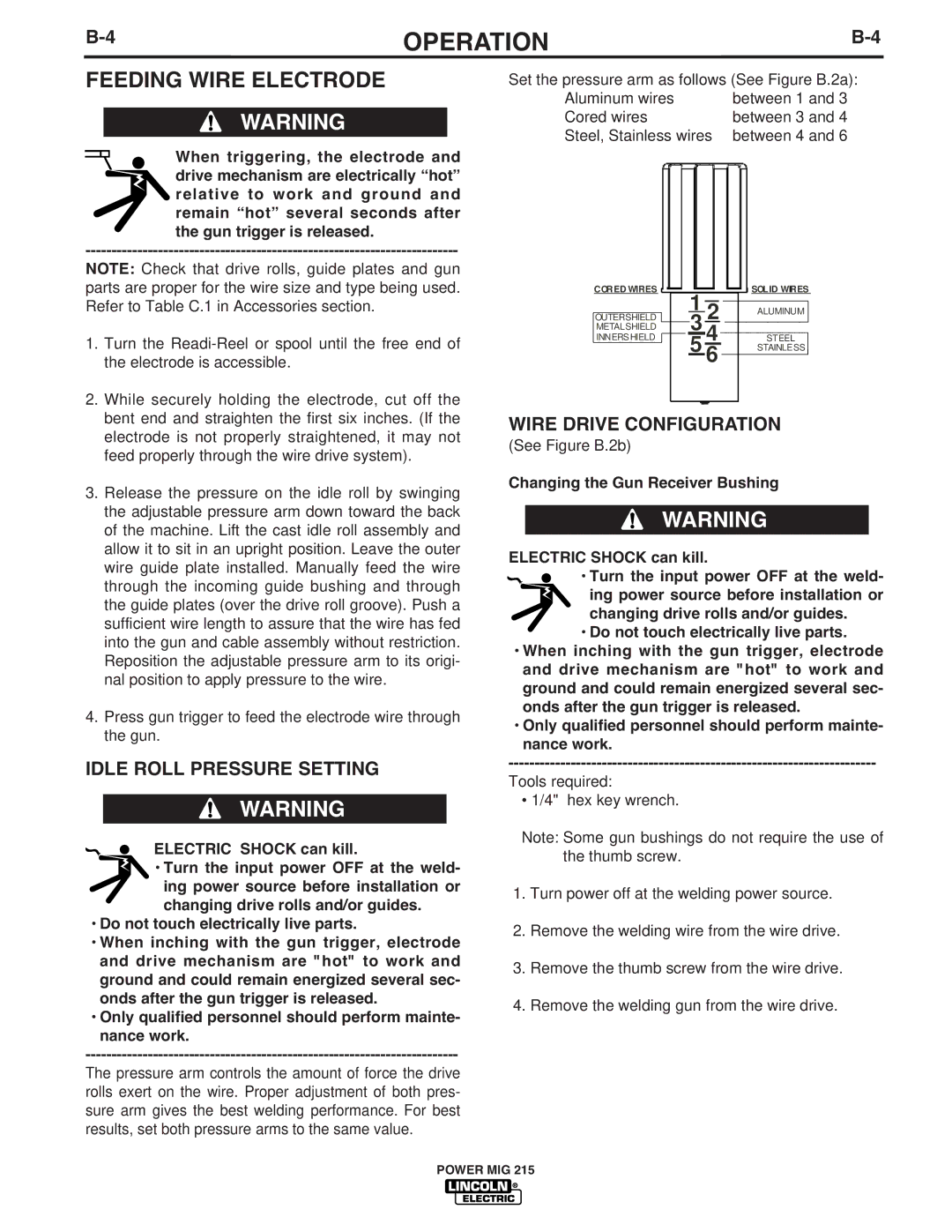
| Set the pressure arm as follows (See Figure B.2a): | |||
| Cored wires |
|
| between 3 and 4 | |
When triggering, the electrode and | Steel, Stainless wires | between 4 and 6 | |||
drive mechanism are electrically “hot” |
|
|
|
| |
relative to work and ground and |
|
|
|
| |
remain “hot” several seconds after |
|
|
|
| |
the gun trigger is released. |
|
|
|
|
|
|
|
|
| ||
NOTE: Check that drive rolls, guide plates and gun |
|
|
|
| |
parts are proper for the wire size and type being used. | OU TER SHIELD | 1 2 | ALU M INU M | ||
Refer to Table C.1 in Accessories section. |
| ||||
1. Turn the | C OR ED W IR ES |
|
| SOLID W IR ES | |
M ETALSHIELD | 5 |
| STAINLE SS | ||
the electrode is accessible. |
| INN ERS HIELD |
| 6 | STEEL |
|
|
| 4 | ||
2. While securely holding the electrode, cut off the | WIRE DRIVE CONFIGURATION | ||||
electrode is not properly straightened, it may not | |||||
bent end and straighten the first six inches. (If the | (See Figure B.2b) |
|
|
| |
feed properly through the wire drive system). |
|
|
| ||
3. Release the pressure on the idle roll by swinging | Changing the Gun Receiver Bushing | ||||
of the machine. Lift the cast idle roll assembly and | WARNING | ||||
the adjustable pressure arm down toward the back |
|
|
|
| |
allow it to sit in an upright position. Leave the outer | ELECTRIC SHOCK can kill. |
| |||
wire guide plate installed. Manually feed the wire | • Turn the input power OFF at the weld- | ||||
through the incoming guide bushing and through | ing power source before installation or | ||||
the guide plates (over the drive roll groove). Push a | changing drive rolls and/or guides. | ||||
sufficient wire length to assure that the wire has fed | • Do not touch electrically live parts. | ||||
into the gun and cable assembly without restriction. | • When inching with the gun trigger, electrode | ||||
Reposition the adjustable pressure arm to its origi- | and drive mechanism are "hot" to work and | ||||
nal position to apply pressure to the wire. |
| ground and could remain energized several sec- | |||
4. Press gun trigger to feed the electrode wire through | onds after the gun trigger is released. | ||||
• Only qualified personnel should perform mainte- | |||||
the gun. |
| nance work. |
|
|
|
IDLE ROLL PRESSURE SETTING |
| Tools required: |
|
|
|
WARNING |
| ||||
| • 1/4" hex key wrench. |
|
|
| |
ELECTRIC SHOCK can kill. |
| Note: Some gun bushings do not require the use of | |||
• Turn the input power OFF at the weld- | the thumb screw. |
|
|
| |
ing power source before installation or | 1. Turn power off at the welding power source. | ||||
changing drive rolls and/or guides. | |||||
• Do not touch electrically live parts. |
| 2. Remove the welding wire from the wire drive. | |||
• When inching with the gun trigger, electrode | |||||
and drive mechanism are "hot" to work and | 3. Remove the thumb screw from the wire drive. | ||||
ground and could remain energized several sec- | |||||
onds after the gun trigger is released. |
| 4. Remove the welding gun from the wire drive. | |||
• Only qualified personnel should perform mainte- | |||||
nance work. |
|
|
|
|
|
|
|
|
| ||
The pressure arm controls the amount of force the drive |
|
|
|
| |
rolls exert on the wire. Proper adjustment of both pres- |
|
|
|
| |
sure arm gives the best welding performance. For best |
|
|
|
| |
results, set both pressure arms to the same value. |
|
|
|
| |
POWER MIG 215