INSTALLATION | ||
|
|
|
SELECT AND INSTALL GUN CONSUMABLE PARTS
1. LINER ASSEMBLY
|
|
|
|
|
| TABLE A.2 | ||
|
|
| KP Nos. for Gun Model | |||||
| Wire Diameter | 350 amp |
| 550 amp | ||||
0.035 |
|
|
|
| ||||
| 0.045 |
|
|
| ||||
| 0.052 |
|
|
| ||||
| 1/16 |
|
|
|
| |||
| 5/64 |
| none |
|
|
| ||
| 3/32 |
| none |
|
|
| ||
Note that the Magnum Pro 350 and 550 amp fume guns use the same liner assemblies as the Magnum 300 and 550 MIG gun products, respectively.
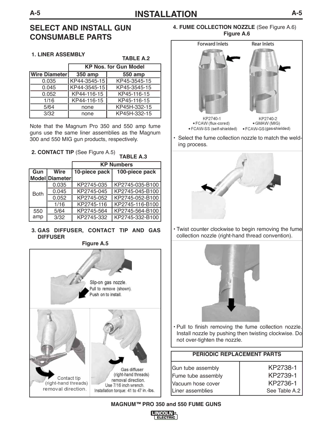
2.CONTACT TIP (See Figure A.5)
TABLE A.3
KP Numbers
Gun Wire
0.035
0.045
0.052
1/16
5/64
3/32
3.GAS DIFFUSER, CONTACT TIP AND GAS DIFFUSER
Figure A.5
4.FUME COLLECTION NOZZLE (See Figure A.6)
Figure A.6
•Select the fume collection nozzle to match the weld- ing process.
•Twist counter clockwise to begin removing the fume collection nozzle
•Pull to finish removing the fume collection nozzle. Install nozzle by pushing then twisting clockwise. Do not
PERIODIC REPLACEMENT PARTS
Gun tube assembly | |
Fume tube assembly | |
Vacuum hose cover | |
Liner assemblies | See Table A.2 |
