W A V E F O R M C O N T R O L T E C H N O L O G Y T M
APPLICATION
Tandem MIG | 7/16 |
|
|
Comparing High-Speed Tandem MIG
To Single Wire GMAW Processes
Travel Speed Comparison
| Typical Travel Speeds |
140 | Single Wire GMAW vs Tandem MIG |
|
|
Single Wire GMAW
| 120 |
|
|
| Tandem MIG |
|
|
|
|
| |
| 100 |
|
|
|
|
Travel |
|
|
|
|
|
Speed | 80 |
|
|
|
|
(ipm) |
|
|
|
| |
|
|
|
|
| |
| 60 |
|
|
|
|
| 40 |
|
|
|
|
| 2mm | 2.5mm | 3mm | 4mm | 5mm |
Lap Weld Size
Comparing High-Deposition Tandem MIG
To Single Wire GMAW Process
Higher Deposition rates
Problem - Single Wire GMAW
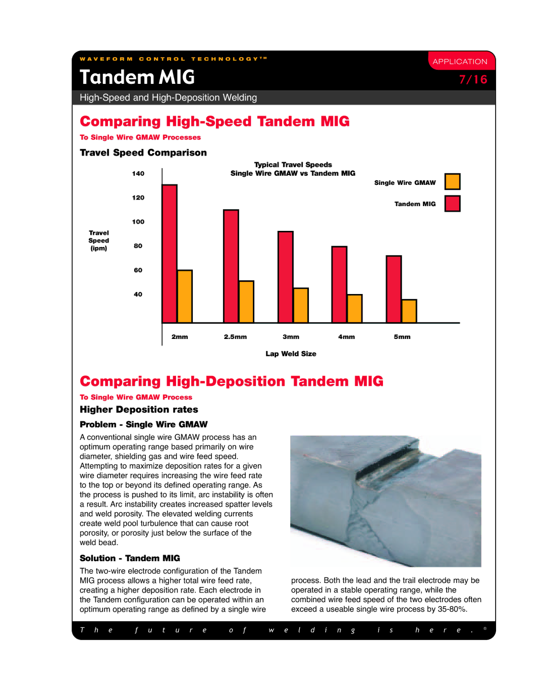
A conventional single wire GMAW process has an optimum operating range based primarily on wire diameter, shielding gas and wire feed speed.
Attempting to maximize deposition rates for a given wire diameter requires increasing the wire feed rate to the top or beyond its defined operating range. As the process is pushed to its limit, arc instability is often a result. Arc instability creates increased spatter levels and weld porosity. The elevated welding currents create weld pool turbulence that can cause root porosity, or porosity just below the surface of the weld bead.
Solution - Tandem MIG
The
process. Both the lead and the trail electrode may be operated in a stable operating range, while the combined wire feed speed of the two electrodes often exceed a useable single wire process by
T h e | f u t u r e | o f | w e l d i n g | i s | h e r e . | ® |
| ||||||
|
|
|
|
|
|
|
