INSTALLATION | ||
|
|
|
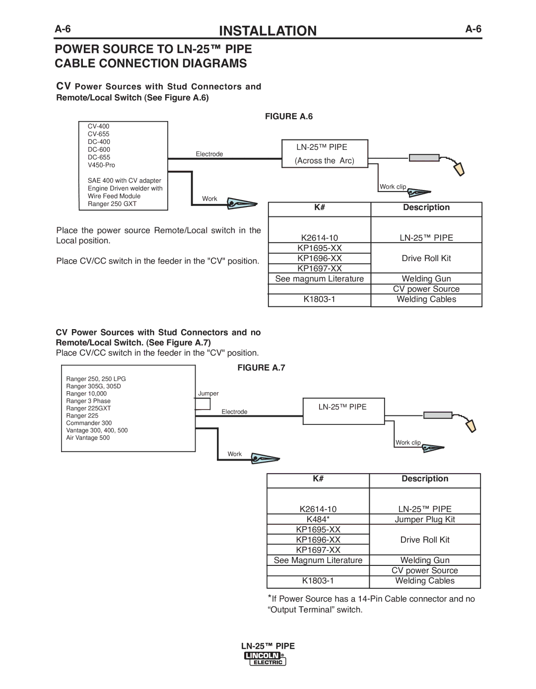
POWER SOURCE TO LN-25™ PIPE
CAbLE CONNECTION DIAGRAMS
CV Power Sources with Stud Connectors and Remote/Local Switch (See Figure A.6)
SAE 400 with CV adapter
Engine Driven welder with
Wire Feed ModuleWork
Ranger 250 GXT
Place the power source Remote/Local switch in the Local position.
Place CV/CC switch in the feeder in the "CV" position.
FIGURE A.6
| Work clip |
|
|
K# | Description |
|
|
| |
Drive Roll Kit | |
| |
See magnum Literature | Welding Gun |
| CV power Source |
Welding Cables | |
|
|
CV Power Sources with Stud Connectors and no
Remote/Local Switch. (See Figure A.7)
Place CV/CC switch in the feeder in the "CV" position.
| FIGURE A.7 |
| |
Ranger 250, 250 LPG |
|
|
|
Ranger 305G, 305D | Jumper |
|
|
Ranger 10,000 |
|
| |
Ranger 3 Phase |
|
| |
Ranger 225GXT | Electrode |
| |
Ranger 225 |
|
| |
|
|
| |
Commander 300 |
|
|
|
Vantage 300, 400, 500 |
|
|
|
Air Vantage 500 |
|
| Work clip |
|
|
| |
| Work |
|
|
|
|
|
|
|
| K# | Description |
|
|
|
|
|
| ||
|
| K484* | Jumper Plug Kit |
|
|
| |
|
| Drive Roll Kit | |
|
|
| |
|
| See Magnum Literature | Welding Gun |
|
|
| CV power Source |
|
| Welding Cables | |
|
|
|
|
*If Power Source has a