OPERATION | ||
|
|
|
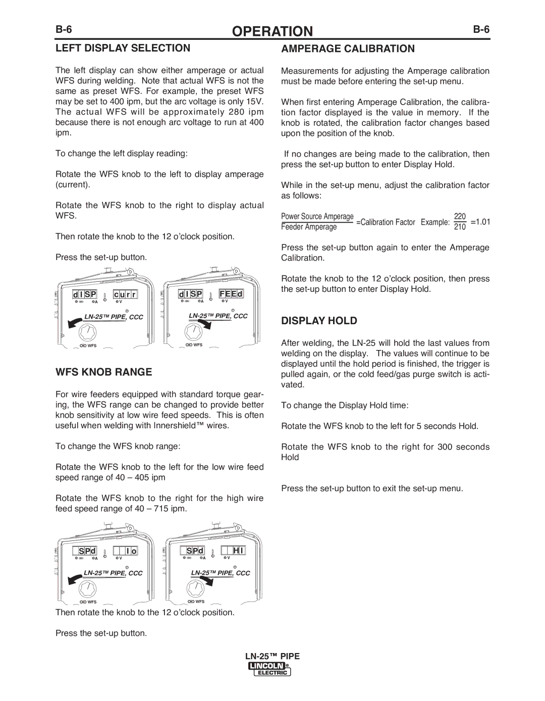
LEFT DISPLAY SELECTION
The left display can show either amperage or actual WFS during welding. Note that actual WFS is not the same as preset WFS. For example, the preset WFS may be set to 400 ipm, but the arc voltage is only 15V. The actual WFS will be approximately 280 ipm because there is not enough arc voltage to run at 400 ipm.
To change the left display reading:
Rotate the WFS knob to the left to display amperage (current).
Rotate the WFS knob to the right to display actual WFS.
Then rotate the knob to the 12 o’clock position.
AMPERAGE CALIbRATION
Measurements for adjusting the Amperage calibration must be made before entering the
When first entering Amperage Calibration, the calibra- tion factor displayed is the value in memory. If the knob is rotated, the calibration factor changes based upon the position of the knob.
If no changes are being made to the calibration, then press the
While in the
Power Source Amperage | =Calibration Factor Example: | 220 | =1.01 | |
Feeder Amperage |
| 210 | ||
Press the
d I SP | c u r r |
O O A | V |
![]()
![]() d
d![]()
![]() I
I ![]()
![]() SP
SP![]()
![]()
![]()
![]()
![]()
![]() FEE
FEE![]()
![]()
![]() d
d![]()
![]()
O O A | V |
Press the
Rotate the knob to the 12 o’clock position, then press the
DISPLAY HOLD
O O WFS | O O WFS |
WFS KNOb RANGE
For wire feeders equipped with standard torque gear- ing, the WFS range can be changed to provide better knob sensitivity at low wire feed speeds. This is often useful when welding with Innershield™ wires.
To change the WFS knob range:
Rotate the WFS knob to the left for the low wire feed speed range of 40 – 405 ipm
Rotate the WFS knob to the right for the high wire feed speed range of 40 – 715 ipm.
SPd | I o | SPd | H I | |
O O A | V | O O | A | V |
O O WFS |
| O O WFS |
| |
Then rotate the knob to the 12 o’clock position.
Press the
After welding, the
To change the Display Hold time:
Rotate the WFS knob to the left for 5 seconds Hold.
Rotate the WFS knob to the right for 300 seconds Hold
Press the