b-4 OPERATIONb-4
POWER-UP SEQUENCE
All of the LED’s will briefly illuminate during
WIRE FEED SPEED/AMPERAGE DISPLAY
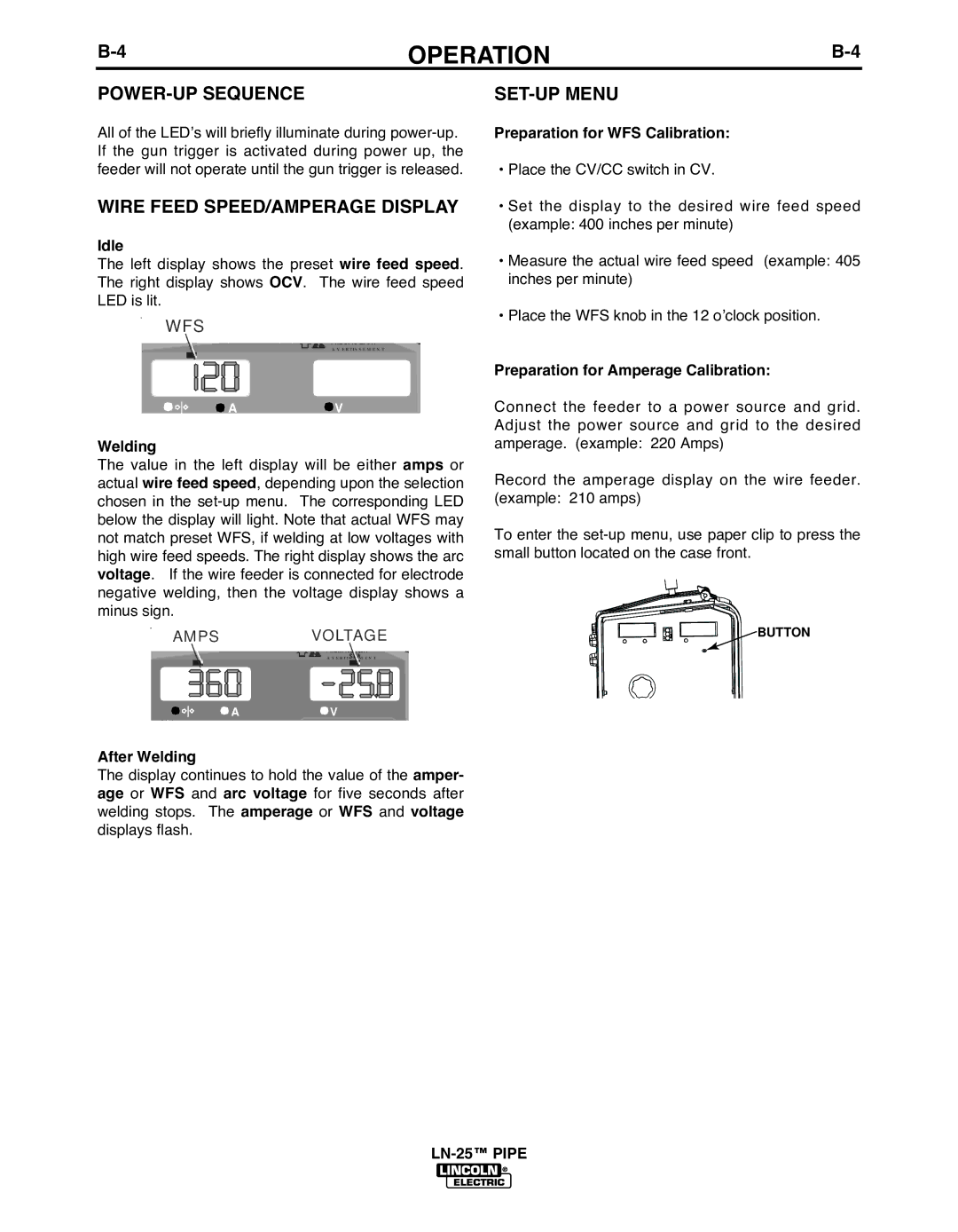
Idle
The left display shows the preset wire feed speed. The right display shows OCV. The wire feed speed LED is lit.
WFS
A V E R T I S S E M E N T
![]() A
A ![]() V
V
Welding
The value in the left display will be either amps or actual wire feed speed, depending upon the selection chosen in the
AMPS VOLTAGE
A V E R T I S S E M E N T
A![]() V
V
After Welding
The display continues to hold the value of the amper- age or WFS and arc voltage for five seconds after welding stops. The amperage or WFS and voltage displays flash.
SET-UP MENU
Preparation for WFS Calibration:
•Place the CV/CC switch in CV.
•Set the display to the desired wire feed speed (example: 400 inches per minute)
•Measure the actual wire feed speed (example: 405 inches per minute)
•Place the WFS knob in the 12 o’clock position.
Preparation for Amperage Calibration:
Connect the feeder to a power source and grid. Adjust the power source and grid to the desired amperage. (example: 220 Amps)
Record the amperage display on the wire feeder. (example: 210 amps)
To enter the
![]()
![]()
![]()
![]()
![]()
![]()
![]()
![]()
![]()
![]()
![]()
![]()
![]()
![]() BUTTON
BUTTON