59A

59

2

D+

W

1

-E12


CR1


TO WELDING


53B

1

3


B+

D-


BOTTOM VIEW


ALTERNATOR ROTOR


GENERATOR


(

SHOWN


)


+Y

-


ALTERNATOR


SLIP RINGS


+ -


B

610


4

6


SLIP RING NEAREST


B


W


TERMINAL


U


7

9


R1


STRIP

R

600


58D


TO IRON


+


IDLER

U


A

B


50


R


600


P.C.

R


AC


AC

N


BOARD W

57


8


41


61


FUEL


Y

56A


42


-


600A


60B


SOLENOID


602


60D


41


58C

60F


58A

ENGINE


7


W

602


58B


115 VOLT


15A.


Y


PROTECTION


IDLER


RELAY


RECEPTACLE


FUSE


42


START


56


SOLENOID


Y


+


IGNITION


60C


FUSE (SFE-14)


POTENTIOMETER

SELECTOR


IDLER


SWITCH


ENGINE


602A

SWITCH


SWITCH


OIL TEMPERATURE


R


G NO NC S B


HOUR METER


60


3

SENSOR


ALTERNATOR


W


60A


54B


AUXILIARY


CB1


POWER

U


54


54A 58

4


(30 AMP)


WINDINGS


50A

53A


53


55


51A


OIL PRESSURE


52


60E


5

SENSOR

IICLASSIC— DEUTZ ENGINE


B

B


S I


G


A


STARTING


GND


DIAGRAMS


GAUGE

6


CV ADAPTER


CURRENT


N


MOTOR


OIL PRESSURE


5 4

3 2 1


TRANSFORMER


50


U


51


230 VOLT


CR2 REED

WELDER


RELAY


U


LEAD BLOCK


RECEPTACLE


R

N

N

509


+ A


G


+


U

U

503


N

POSITIVE CV &


VV OUTPUT


NEGATIVE


TERMINAL


-


VV OUTPUT

POS


CB2


TERMINAL


NEG


(15 AMP)


REMOTE CONTROL (OPTIONAL)


W

-

TO WELDING


W

Y

+

GENERATOR


4

8


REMOTE CONTROL PANEL & SWITCH


CV ADAPTER


Y


SA-250 THERMOSTAT


3

7


ASSEMBLY


RESISTORS


COPPER


608


CONNECT TO NEGATIVE


2

6


COPPER


TERMINAL


609


PLUG FOR


BRUSH HOLDER


1

5


TERMINAL


REMOTE CONTROL


#2 HEAVY LEAD


POTENTIOMETER


W


NEGATIVE CV OUTPUT TERMINAL


B

GROUND TERM.


PIN CONFIGURATION


(WIDE SLOT)


B


ON ENGINE


G


CONNECTOR


*


41


W


602


GROUND TERM.


G


SEE

600


(WIDE SLOT)


ELECTRICAL SYMBOLS PER E1537


BELOW


CONNECT


42


LEAD COLOR CODE


TO CASE


SWITCH FOR


B-BLACK

R-RED


G-GREEN

U-BLUE


LOCAL OR REMOTE


N-BROWN

W-WHITE


CONTROL SHOWN IN


Y-YELLOW


CONTROL PANEL COMPONENTS


LOCAL POSITION.


REMOTE CONTROL


SHOWN AS VIEWED FROM REAR.


*

WITH MACHINE NOT RUNNING, REMOVE JUMPER 42 TO


POTENTIOMETER BOX


600 AT THE TERMINAL STRIP. CONNECT THESE LEADS

CV ADAPTER CONTROL LEADS

A

E-12

TO THE CORRESPONDING NUMBERS AT THE TERMINAL

ARE NOT COLOR CODED ON


STRIP.

ALL UNITS

L9071


Page 41
Image 41
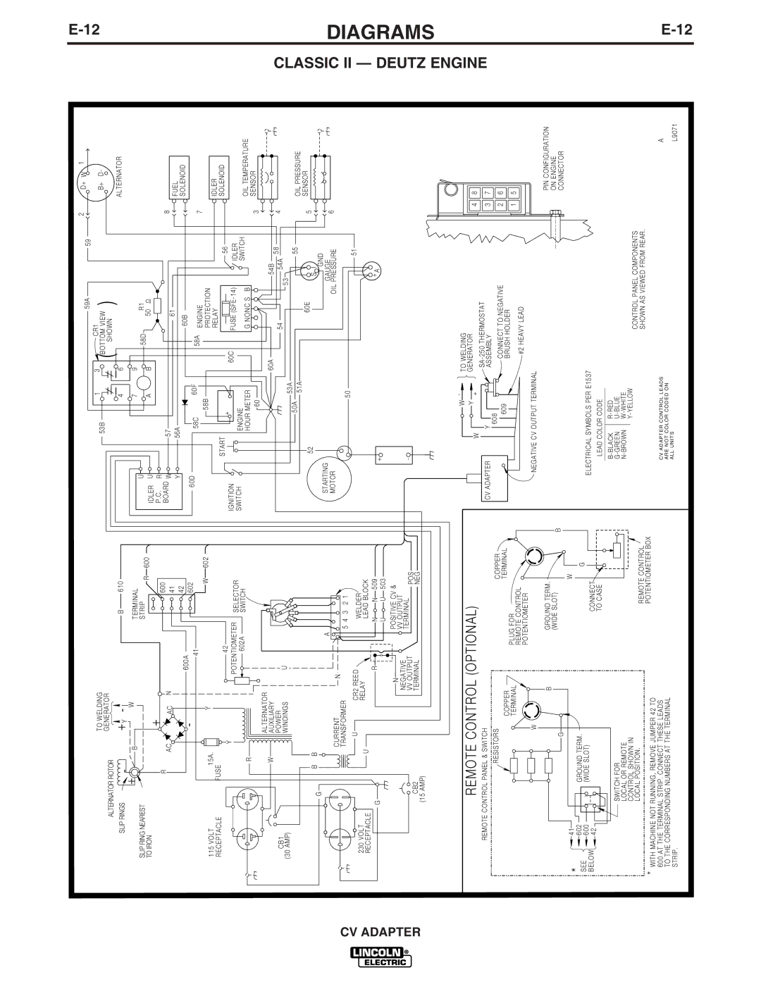
Lincoln Electric IM309-D manual E12

IM309-D specifications

Lincoln Electric IM309-D is a cutting-edge multi-process welding machine designed to meet the demands of both professionals and hobbyists in various welding applications. This machine stands out in the marketplace due to its innovative features, robust build, and advanced technologies that enhance usability and performance.

One of the main features of the IM309-D is its multi-process capability. The machine can seamlessly switch between MIG, TIG, and Stick welding processes, making it versatile for different welding tasks. This flexibility is particularly valuable in environments where different welding techniques are required for distinct projects.

The IM309-D employs advanced digital controls that offer precise welding parameters and settings adjustment. This level of control enables users to achieve optimal quality in their welds, regardless of the material type or thickness. The intuitive interface makes it user-friendly, allowing even less experienced welders to navigate its features with ease.

In terms of power, the IM309-D is equipped with a robust duty cycle that ensures consistent performance during extended welding tasks. It supports a wide voltage input, allowing it to operate effectively in various industrial or construction site settings. The machine is designed to be energy-efficient, reducing operational costs without compromising performance.

One of the prominent technologies utilized in the IM309-D is its Auto-Set feature. This intelligent technology automatically calculates optimal settings based on the material type and thickness, saving time and minimizing guesswork for the welder. Additionally, it incorporates an advanced cooling system that prevents overheating, ensuring reliability during prolonged use.

Safety is another critical focus of the IM309-D design. The machine features multiple safety mechanisms, including overload protection and thermal shutdown features that protect both the equipment and the operator. The robust construction also ensures durability, making it suitable for rigorous work environments.

Overall, the Lincoln Electric IM309-D stands out for its exceptional combination of versatility, efficiency, and safety. With its advanced technology and user-friendly interface, it is a reliable choice for welders looking to enhance their productivity and achieve superior results in their welding projects. Whether used in a professional shop or a home workshop, the IM309-D delivers impressive performance and value.