11 |
|
|
|
|
|
|
|
| 11 |
| ||
| Welder Controls - Function and Operation | a. | Welding | |||||||||
|
|
|
|
|
|
|
|
| When the electrode touches the work, the welding | |||
|
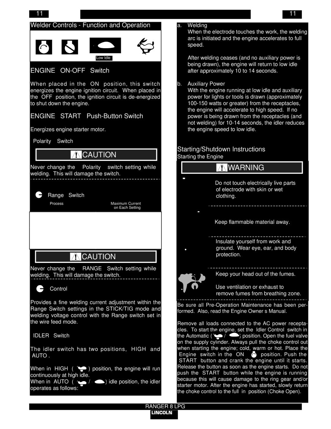
| Explanation of Symbols that Appear on this Equipment |
| |||||||||
|
|
|
|
|
|
|
|
|
|
| arc is initiated and the engine accelerates to full | |
|
|
|
|
|
|
|
|
|
|
| ||
|
|
|
|
|
|
|
|
|
|
| ||
|
|
|
|
|
|
|
|
|
|
| speed. | |
|
|
|
|
|
|
|
|
|
|
| After welding ceases (and no auxiliary power is | |
|
|
|
|
|
|
|
|
|
|
| ||
|
|
|
| OFF |
|
|
|
|
| |||
|
|
|
|
|
|
|
|
| ||||
|
| ON |
|
| Low Idle | High Idle |
| |||||
|
|
|
|
|
|
|
|
|
|
| being drawn), the engine will return to low idle | |
| ENGINE |
|
| |||||||||
|
|
| after approximately 10 to 14 seconds. | |||||||||
| When placed in the “ON” position, this switch | b. | Auxiliary Power | |||||||||
| energizes the engine ignition circuit. | When placed in |
| With the engine running at low idle and auxiliary | ||||||||
| the “OFF” position, the ignition circuit is |
| power for lights or tools is drawn (approximately | |||||||||
| to shut down the engine. |
|
|
|
|
| ||||||
| ENGINE “START” |
| the engine will accelerate to high speed. If no | |||||||||
|
| power is being drawn from the receptacles (and | ||||||||||
|
|
|
|
|
|
|
|
|
|
| not welding) for | |
| Energizes engine starter motor. |
|
| the engine speed to low idle. | ||||||||
“Polarity” Switch
![]() CAUTION
CAUTION
Never change the “Polarity” switch setting while welding. This will damage the switch.
“ | Range” Switch |
|
| Process | Maximum Current |
|
| on Each Setting |
|
| |
STICK/TIG - CC | 50, 70, 90 | |
6 | Range Settings | 125, 175, 210 DC/225 AC |
|
| |
WIRE FEED - CV |
| |
1 | Range Setting | 200 |
|
|
|
![]() CAUTION
CAUTION
Never change the “RANGE” Switch setting while welding. This will damage the switch.
“![]() Control”
Control”
Provides a fine welding current adjustment within the Range Switch settings in the STICK/TIG mode and welding voltage control with the Range switch set in the wire feed mode.
“IDLER” Switch
The idler switch has two positions, “HIGH” and “AUTO”.
When in “HIGH” ( ![]() ) position, the engine will run continuously at high idle.
) position, the engine will run continuously at high idle.
When in “AUTO” ( ![]() /
/ ![]()
![]() ) idle position, the idler operates as follows:
) idle position, the idler operates as follows: ![]()
Starting/Shutdown Instructions
Starting the Engine
![]() WARNING
WARNING
• Do not touch electrically live parts of electrode with skin or wet clothing.
•Keep flammable material away.
•Insulate yourself from work and
ground. Wear eye, ear, and body protection.
• Keep your head out of the fumes.
• Use ventilation or exhaust to remove fumes from breathing zone.
Be sure all
Remove all loads connected to the AC power recepta- cles. To start the engine, set the “Idler Control” switch in
the Automatic ( ![]() /
/![]()
![]() ) position. Open the fuel valve on the supply cylinder. Always pull the choke control out when starting the engine; cold, warm or hot. Place the
) position. Open the fuel valve on the supply cylinder. Always pull the choke control out when starting the engine; cold, warm or hot. Place the
“Engine” switch in the “ON” ![]() position. Push the “START” button and crank the engine until it starts. Release the button as soon as the engine starts. Do not push the “START” button while the engine is running because this will cause damage to the ring gear and/or starter motor. After the engine has started, slowly return the choke control to the full “in” position (Choke Open).
position. Push the “START” button and crank the engine until it starts. Release the button as soon as the engine starts. Do not push the “START” button while the engine is running because this will cause damage to the ring gear and/or starter motor. After the engine has started, slowly return the choke control to the full “in” position (Choke Open).