OPERATION | |||
|
|
|
|
|
|
|
| Arc Volts Used |
|
|
|
| ||
Desired |
|
|
|
|
|
|
|
|
|
|
|
|
|
|
|
|
|
|
|
| |
In/Min | 16 | 18 | 20 | 22 | 24 | 26 | 28 | 30 | 32 | 34 |
|
|
|
|
|
|
|
|
|
|
|
50 | 109 | 97 | 88 | 80 | 73 | 67 | 63 | 58 | 55 | 51 |
60 | 131 | 117 | 105 | 95 | 88 | 81 | 75 | 70 | 66 | 62 |
70 | 153 | 136 | 123 | 111 | 102 | 94 | 88 | 82 | 77 | 72 |
80 | 175 | 156 | 140 | 127 | 117 | 108 | 100 | 93 | 88 | 82 |
90 | 197 | 175 | 158 | 143 | 131 | 121 | 113 | 105 | 98 | 93 |
|
|
|
|
|
|
|
|
|
|
|
100 | 219 | 194 | 175 | 159 | 146 | 135 | 125 | 117 | 109 | 103 |
110 | 241 | 214 | 193 | 175 | 160 | 148 | 138 | 128 | 120 | 113 |
120 | 263 | 233 | 210 | 191 | 175 | 162 | 150 | 140 | 131 | 124 |
130 | 284 | 253 | 228 | 207 | 190 | 175 | 163 | 152 | 142 | 134 |
140 | 306 | 272 | 245 | 223 | 204 | 188 | 175 | 163 | 153 | 144 |
|
|
|
|
|
|
|
|
|
|
|
150 | 328 | 292 | 263 | 239 | 219 | 202 | 188 | 175 | 164 | 154 |
160 | 350 | 311 | 280 | 255 | 233 | 215 | 200 | 187 | 175 | 165 |
170 | 372 | 331 | 298 | 270 | 248 | 229 | 213 | 198 | 186 | 175 |
180 | 394 | 350 | 315 | 286 | 263 | 242 | 225 | 210 | 197 | 185 |
190 | 416 | 369 | 333 | 302 | 277 | 256 | 238 | 222 | 208 | 196 |
|
|
|
|
|
|
|
|
|
|
|
200 | 438 | 389 | 350 | 318 | 292 | 269 | 250 | 233 | 219 | 206 |
210 | 459 | 408 | 368 | 334 | 306 | 283 | 263 | 245 | 230 | 216 |
220 | 481 | 428 | 385 | 350 | 321 | 296 | 275 | 257 | 241 | 226 |
230 | 503 | 447 | 403 | 366 | 335 | 310 | 288 | 268 | 252 | 237 |
240 | 525 | 467 | 420 | 382 | 350 | 323 | 300 | 280 | 263 | 247 |
|
|
|
|
|
|
|
|
|
|
|
250 | 547 | 486 | 438 | 398 | 365 | 337 | 313 | 292 | 273 | 257 |
260 | 569 | 506 | 455 | 414 | 379 | 350 | 325 | 303 | 284 | 268 |
270 | 591 | 525 | 473 | 430 | 394 | 365 | 338 | 315 | 295 | 278 |
280 | 613 | 544 | 490 | 445 | 408 | 377 | 350 | 327 | 306 | 288 |
290 | 634 | 564 | 508 | 461 | 423 | 390 | 363 | 338 | 317 | 299 |
|
|
|
|
|
|
|
|
|
|
|
300 | 656 | 583 | 525 | 477 | 438 | 404 | 375 | 350 | 328 | 309 |
310 | 678 | 603 | 543 | 493 | 452 | 417 | 388 | 362 | 339 | 319 |
320 | 700 | 622 | 560 | 509 | 467 | 431 | 400 | 373 | 350 | 329 |
330 |
| 642 | 578 | 525 | 481 | 444 | 413 | 385 | 361 | 340 |
340 |
| 661 | 595 | 541 | 496 | 458 | 425 | 397 | 372 | 350 |
|
|
|
|
|
|
|
|
|
|
|
350 |
| 681 | 613 | 557 | 510 | 471 | 438 | 408 | 383 | 360 |
360 |
| 700 | 630 | 572 | 526 | 484 | 450 | 420 | 394 | 370 |
380 |
|
| 666 | 604 | 554 | 512 | 472 | 444 | 416 | 392 |
400 |
|
| 700 | 636 | 584 | 538 | 500 | 466 | 438 | 412 |
420 |
|
|
| 668 | 612 | 566 | 526 | 490 | 460 | 432 |
|
|
|
|
|
|
|
|
|
|
|
440 |
|
|
| 700 | 642 | 592 | 550 | 514 | 482 | 452 |
460 |
|
|
|
| 670 | 620 | 576 | 536 | 504 | 472 |
480 |
|
|
|
| 700 | 646 | 600 | 560 | 526 | 494 |
500 |
|
|
|
|
| 674 | 626 | 584 | 546 | 514 |
|
|
|
|
|
|
|
|
|
|
|
520 |
|
|
|
|
| 700 | 650 | 606 | 568 | 536 |
540 |
|
|
|
|
|
| 676 | 630 | 590 | 556 |
560 |
|
|
|
|
|
| 700 | 654 | 612 | 576 |
580 |
|
|
|
|
|
|
| 676 | 634 | 598 |
600 |
|
|
|
|
|
|
| 700 | 656 | 618 |
|
|
|
|
|
|
|
|
|
|
|
620 |
|
|
|
|
|
|
|
| 678 | 638 |
640 |
|
|
|
|
|
|
|
| 700 | 658 |
660 |
|
|
|
|
|
|
|
|
| 680 |
680 |
|
|
|
|
|
|
|
|
| 700 |
700 |
|
|
|
|
|
|
|
|
|
|
|
|
|
|
|
|
|
|
|
|
|
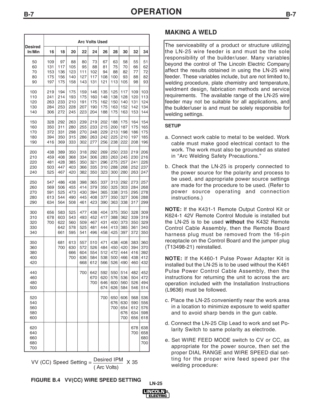
VV(CC) Speed Setting = Desired IPM X 35 ( Arc Volts)
MAKING A WELD
The serviceability of a product or structure utilizing the
SETUP
a. Connect work cable to metal to be welded. Work cable must make good electrical contact to the work. The work must also be grounded as stated in “Arc Welding Safety Precautions.”
b.Check that the
NOTE: If the
NOTE: If the
c.Place the
d.Connect the
e.Set WIRE FEED MODE switch to CV or CC, as appropriate for the power source, then set the proper DIAL RANGE and WIRE SPEED dial set- ting for the proper wire feed speed per the welding procedure: