INSTALLATION |
Work Cable Installation
Refer to Figure A.2.
1.Open the wire feed section door on the right side of the SP
2.Pass the end of the work cable that has the termi- nal lug with the smaller hole through the Work Cable Access Hole (1) in the case front.
3.Route the cable under the feedplate (6) and in front of the Wire Feed Motor.
4.For Innershield Only: Refer to Figure A.2. As delivered, the machine is connected for negative electrode polarity. This is the appropriate configu- ration for the Innershield process. To complete installation, use the provided wing nut to connect the work cable’s terminal lug to the positive (+) out- put terminal (4) located above the Wire Feed Gearbox (5). Make sure that both wing nuts are tight.
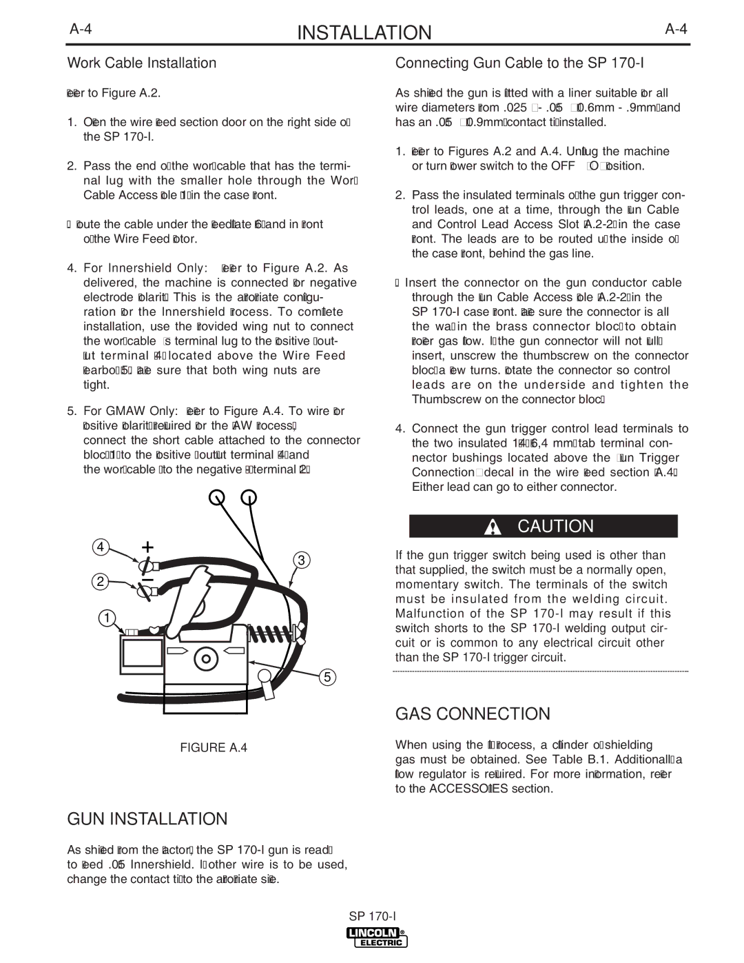
5.For GMAW Only: Refer to Figure A.4. To wire for positive polarity (required for the GMAW process), connect the short cable attached to the connector block (1) to the positive (+) output terminal (4) and the work cable (3) to the negative
Connecting Gun Cable to the SP 170-I
As shipped the gun is fitted with a liner suitable for all wire diameters from .025”
1.Refer to Figures A.2 and A.4. Unplug the machine or turn power switch to the OFF “O” position.
2.Pass the insulated terminals of the gun trigger con- trol leads, one at a time, through the Gun Cable and Control Lead Access Slot
3.Insert the connector on the gun conductor cable through the Gun Cable Access Hole
4.Connect the gun trigger control lead terminals to the two insulated 1/4" (6,4 mm) tab terminal con- nector bushings located above the “Gun Trigger Connection” decal in the wire feed section (A.4). Either lead can go to either connector.
4
3
2 ![]()
![]()
1
5
FIGURE A.4
GUN INSTALLATION
As shipped from the factory, the SP
CAUTION
If the gun trigger switch being used is other than that supplied, the switch must be a normally open, momentary switch. The terminals of the switch must be insulated from the welding circuit. Malfunction of the SP
GAS CONNECTION
When using the MIG process, a cylinder of shielding gas must be obtained. See Table B.1. Additionally a flow regulator is required. For more information, refer to the ACCESSORIES section.
SP