MAINTENANCE |
COMPONENT
REPLACEMENT
PROCEDURES
CHANGING THE CONTACT TIP (These instructions pertain to the Lincoln Electric® gun. The instructions for the Magnum™ 100L gun, are similar except that the gas nozzle is threaded.)
1.Refer to Figure D.2a or D.2b. Remove the gas noz- zle from the gun by pulling and rotating it clockwise off the diffuser. (Threadless slip fit).
2.Remove the existing contact tip from the gun by gripping it with pliers and twisting
3.Insert new tip into diffuser. Grip it with pliers, push tip into diffuser until it bottoms, then twist clockwise to tighten.
4.Replace gas nozzle.
CHANGING DRIVE ROLL
The drive roll has two grooves; one for .023"
.030" (0.8 mm) solid and .035" (0.9 mm)
If .023"/.025" (0.6mm) wire is to be used, the drive roll must be reversed as follows:
1.Connect the machine to its rated input power per instructions in Installation section.
2.Release the
3.Turn the power switch to ON (marked “I”).
4.Set the wire speed to minimum and jog the drive unit with the trigger switch until the drive roll set screw is facing up.
CAUTION
7.Remove the drive roll, flip over and reinstall with the
.023/.025" (0.6mm) groove (the smaller groove) closest to the gearbox.
8.Push a length of straightened welding wire through the wire feeder guide tubes and adjust the position of the drive roll so that the groove is centered on the wire. Make certain the set screw is located on the flat portion of the shaft and tighten.
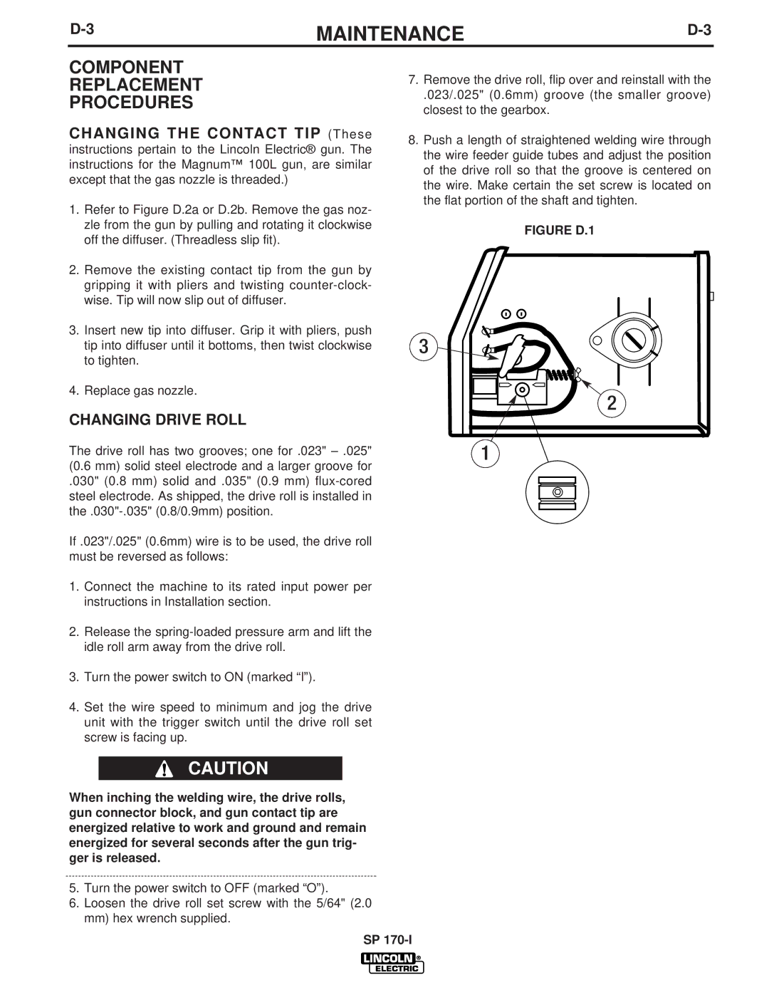
FIGURE D.1
3 ![]()
![]()
![]()
2
1
When inching the welding wire, the drive rolls, gun connector block, and gun contact tip are energized relative to work and ground and remain energized for several seconds after the gun trig- ger is released.
5.Turn the power switch to OFF (marked “O”).
6.Loosen the drive roll set screw with the 5/64" (2.0 mm) hex wrench supplied.
SP