Manuals
/
Lincoln Electric
/
Power Tools
/
Welder
Lincoln Electric
IM846-A
manual
Installation
Models:
IM846-A
1
17
42
42
Download
42 pages
31.1 Kb
14
15
16
17
18
19
20
21
Troubleshooting
Specifications
Install
Error messages
Wiring Diagrams
UP to 4 Wire Feeders Allowed
Dimension
Maintenance
PRObLEMS POSSIbLE Areas
Accessories
Page 17
Image 17
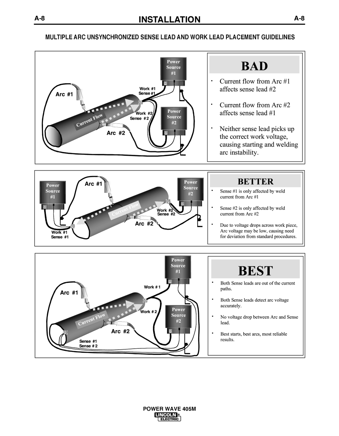
A-8
INSTALLATION
A-8
MULTIPLE ARC UNSYNCHRONIzED SENSE LEAD AND WORK LEAD PLACEMENT GUIDELINES
POWER WAVE 405M
Page 16
Page 18
Page 17
Image 17
Page 16
Page 18
Contents
Safety Depends on You
Power Wave 405M
California Proposition 65 Warnings
Safety
Electric Shock can kill
Iii
Welding and Cutting Sparks can Cause fire or explosion
Précautions DE Sûreté
IvSAFETY
Electromagnetic Compatibility EMC
Methods of Reducing Emissions Mains Supply
On-Line Product Registration
Vii
Please Examine Carton and Equipment For Damage Immediately
TAbLE of Contents
Technical Specifications Power Wave 405M
Installation
Product Ordering Input AC Rated DC Output Weight Dimensions
Information
Single Phase Input
Safety Precautions
Three Phase Input
Select SUITAbLE Location
Negative Electrode Polarity
Output CAbLES, Connections and Limitations
CAbLE INDUCTANCE, and ITS Effects on Pulse Welding
Voltage Sensing
Power Feed Wire Feeder INTERCON- Nections
System Description
Work Voltage Sensing
UP to 4 Wire Feeders Allowed
Configuring the System
Single Head Feeder
UP to 4 Feed Heads Allowed
System that is not Auto Mappable
6INSTALLATIONA-6 Alternate Hard Automatic Application
TWO Power Waves
Welding with Multiple Power Waves
Installation
Electric Shock can kill
Receptacle Specifications
DIP Switch Settings and Locations
Operation
Safety Precautions
General Description
Recommended Processes and Equipment
Required Equipment
Case Front Layout Power Wave 405M
Limitations
Duty Cycle and Time Period
Fringe Procedures
Nominal Procedures
Welding Adjustments
Making a Weld
Current Wave Form CV
Constant Voltage Welding
Synergic CV
Non Synergic CV
PULSE-ON-PULSE GMAW-PP
Pulse Welding
Current Wave Form Pulse
BENEFITS of Pulse on Pulse from Lincoln Electric
Welding Procedures for PULSE-ON-PULSE TAbLE b.2
TIG Gtaw
Smaw
Recommended Welding Procedures for Power Mode Table b.3
Power Mode
Factory Installed
Accessories
Field Installed
Optional Equipment
Periodic Maintenance
Maintenance
Routine Maintenance
Capacitor Discharge Procedure
TROUbLESHOOTING
Error code before the machine is turned off
Using the Status LED to TROUbLESHOOT System PRObLEMS
Error Code # Indication
Error Codes for the Powerwave
PRObLEMS POSSIbLE Areas
TROUbLESHOOTING Guide
Symptoms Misadjustments Course of Action
Recommended
Symptoms
TROUbLESHOOTING
Recommended Course of Action
PRObLEMS
POSSIbLE Areas of Misadjustments
Wiring Diagrams
Diagrams
Connection Diagram Semi-automatic Simple System
Connection Diagram
Dimension Print
Power Wave 405M
Precaucion
Warnung
Top
Page
Image
Contents