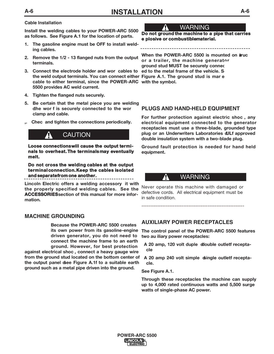
IM871-A specifications
The Lincoln Electric IM871-A is a cutting-edge industrial welding machine that exemplifies the brand's commitment to quality, innovation, and efficiency. Designed specifically for professionals in various sectors, including manufacturing, construction, and maintenance, the IM871-A boasts a range of features that streamline the welding process while ensuring longevity and reliability.One of the standout features of the IM871-A is its advanced inverter technology. This technology not only enhances the machine’s portability but also improves energy efficiency. The inverter design allows for a compact and lightweight unit without sacrificing power output, making it easier for welders to move around job sites while maintaining peak performance. Welders can expect to achieve high-quality welds with minimal spatter, ensuring a clean and professional finish.
The IM871-A is equipped with a multifunctional interface, allowing users to easily navigate through various settings and customize their welding parameters according to specific project requirements. This user-friendly display includes digital readouts for voltage and current, providing real-time information that aids in precision control. Such adaptability makes the IM871-A suitable for a wide range of welding applications, from thin sheet metal to heavier structural components.
Additionally, the Lincoln Electric IM871-A supports multiple welding processes, including MIG, TIG, and Stick welding. This versatility makes it an ideal choice for professionals who require a machine that can handle diverse tasks without the need for multiple setups or equipment. The welder's robust output range further enhances its capabilities, accommodating various materials and thicknesses for both ferrous and non-ferrous metals.
Safety is paramount in any welding operation, and the IM871-A incorporates several features designed to protect the user. These include built-in thermal overload protection, which prevents the machine from overheating during extended use, and an automatic voltage reduction system that ensures the welder remains safe while efficiently managing power.
In summary, the Lincoln Electric IM871-A is a powerful and versatile welding machine built to meet the rigorous demands of industrial applications. With its advanced inverter technology, intuitive user interface, multiple welding process support, and essential safety features, it stands out as a reliable choice for professionals aiming for quality and efficiency in their welding operations. Whether for onsite applications or workshop environments, the IM871-A is engineered to deliver exceptional performance and durability, solidifying its place in the competitive welding market.

