Manuals
/
Lincoln Electric
/
Power Tools
/
Welder
Lincoln Electric
IM910 manual Dimension Print
Models:
IM910
1
32
36
36
Download
36 pages
63.77 Kb
29
30
31
32
33
34
35
36
<
>
Troubleshooting
Specifications
Install
Connection DIAGRAM, Control
Dimension
Wire Drive Configuration
LN-15 Wire Feeder
Errors on the Display
Safety Precautions
Safety
Page 32
Image 32
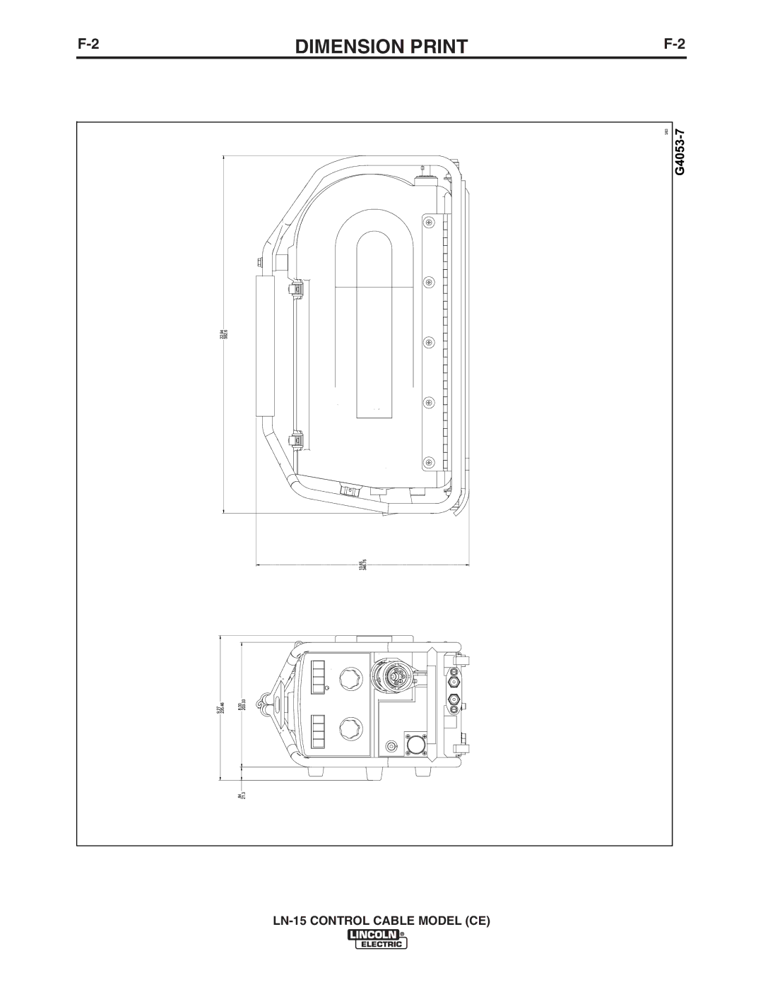
F-2
DIMENSION PRINT
F-2
LN-15
CONTROL CABLE MODEL (CE)
Page 31
Page 33
Page 32
Image 32
Page 31
Page 33
Contents
LN-15 Wire Feeder
Safety Depends on You
Safety
California Proposition 65 Warnings
E C T R I C S H O C K c a n kill
Welding and Cutting Sparks can Cause fire or explosion
Iii
Précautions DE Sûreté
Sûreté Pour Soudage a L’Arc
60974-10
Safety
Vii
Table of Contents
Installation
Technical Specifications LN-15 K1871-3 CE
Installation
Safety Precautions
Location
High Frequency Protection
Power Source Connection
Engine Drive Power Source Connection
Electrode Connection
Work Connection
4INSTALLATIONA-4
Connection DIAGRAM, Control
Guns and Cables Assemblies
Electrode Polarity
Only qualified personnel should perform this operation
Procedure to Install Drive Rolls and Wire Guides
Feeding Wire Electrode
Safety Precautions
Operation
General Description
Across the ARC Model
Figure B.1a
LN-15 POWER-UP Sequence
CV/CC Mode
Spring Tension ARM
WFS Units
Set the pressure arm as follows See Figure B.2a
Wire Drive Configuration
Cold FEED/GAS Purge Switch
Step Trigger Interlock Switch
Flow Meter
Spindle Brake
Shielding GAS Connection
Constant Current Operation
Figure B.3
Figure B.4 CC Wire Speed Setting
Making a Weld
Accessories
Optional Equipment
Maintenance
Routine Maintenance
Periodic Maintenance
Calibration Specification
Troubleshooting
HOW to USE Troubleshooting Guide
Contact your local Lincoln Authorized Field Service Facility
Contact your local Lincoln
Field Service Facility
Your local Lincoln Authorized
Errors on the Display
Fault Code Description Possible Adjustments
Diagrams
LN-15
Dimension Print
LN-15 Control Cable Model CE
Aviso DE
Guards off