INSTALLATION | ||
|
|
|
VEHICLE MOUNTING
![]() WARNING
WARNING
Improperly mounted concentrated loads may cause unstable vehicle handling and tires or other components to fail.
•Only transport this Equipment on serviceable vehicles which are rated and designed for such loads.
•Distribute, balance and secure loads so vehicle is stable under conditions of use.
•Do not exceed maximum rated loads for compo- nents such as suspension, axles and tires.
•Use appropriate nuts bolts and lockwashers to attach the equipment base to the metal bed or frame of vehicle.
•Follow vehicle manufacturer’s instructions.
PRE-OPERATION SERVICE
![]() CAUTION
CAUTION
READ the engine operating and maintenance instructions supplied with this machine.
WARNING
LPG- fuel can cause fire or explosion.
![]() • All leak testing must be done in a well ventilated area free from all potential ignition sources.
• All leak testing must be done in a well ventilated area free from all potential ignition sources.
•Keep sparks and flame away from machine and LPG supply cylinder.
•Do not expose the LPG supply cylinder to temperatures exceeding 120°F (49°C).
•Do not weld on or near the LPG supply cylin- der.
•Do not smoke or allow any potential ignition sources near the LPG supply cylinder.
•Always be certain that the LPG supply cylinder is NOT in the welding circuit. Do not allow either welding cable to come in contact with the supply cylinder.
•Replace the fuel supply hose if there is excessive abrasion, cracks or wear or if the
hose is cut.
FUEL
A lift truck type coupler is provided on the supplied fuel line for easy hand attachment to a lift truck type LPG fuel cylinder. The fuel cylinder must meet D.O.T. Specification
The engine will not develop full power if connected to the vapor outlet.
![]() CAUTION
CAUTION
Be certain that the cylinder valve is CLOSED before attempting to attach the fuel supply hose coupler to the cylinder. Connect the coupler to the fuel cylinder
and tighten by hand.
___________________________________________
After connecting the fuel supply to the supply cylinder, open the valve on the fuel cylinder and leak test by brushing a 50/50 soap and water solution on to the fol- lowing connections:
•Both ends of the fuel hose where it enters the metal connector.
•The threaded fitting on the end of fuel hose attached to the Ranger 250 LPG fuel shut off solenoid.
•The fuel hose coupler and the connection to the cylinder valve.
•The stem of the cylinder valve and where the valve is attached to the top of the cylinder.
•All other fittings on top of the fuel cylinder.
If growing bubbles appear, there is a leak.
Leak test must be performed each time the fuel cylin- der is replaced.
Always close the cylinder valve when the machine is not being used.
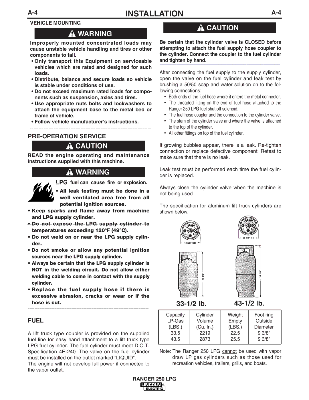
The specification for aluminum lift truck cylinders are shown below:
Capacity | Cylinder | Weight | Foot ring |
Volume | Empty | Outside | |
(LBS.) | (Cu. In.) | (LBS.) | Diameter |
33.5 | 2219 | 22.5 | 9 3/8” |
43.5 | 2873 | 25.5 | 9 3/8” |
|
|
|
|
Note: The Ranger 250 LPG cannot be used with vapor draw LP gas cylinders such as those used for recreation vehicles, trailers, grills, and boats.
RANGER 250 LPG