MAINTENANCE | ||
|
|
|
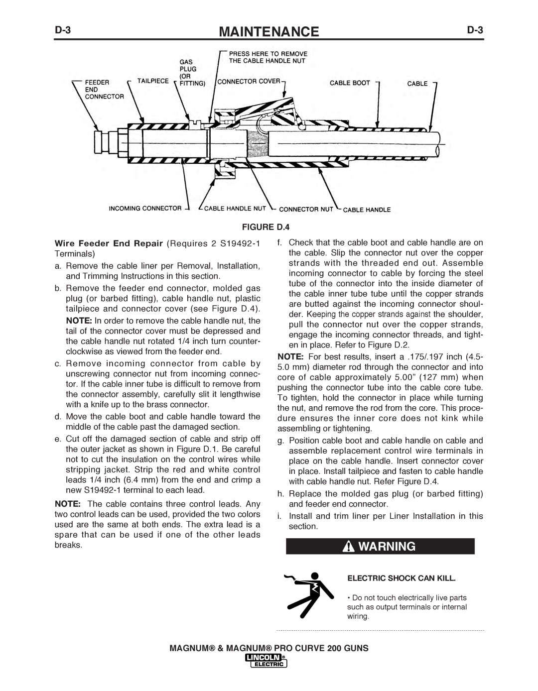
FIGURE D.4
Wire Feeder End Repair (Requires 2 S19492-1 Terminals)
a. Remove the cable liner per Removal, Installation, and Trimming Instructions in this section.
b. Remove the feeder end connector, molded gas plug (or barbed fitting), cable handle nut, plastic tailpiece and connector cover (see Figure D.4). NOTE: In order to remove the cable handle nut, the tail of the connector cover must be depressed and the cable handle nut rotated 1/4 inch turn counter- clockwise as viewed from the feeder end.
c. Remove incoming connector from cable by unscrewing connector nut from incoming connec- tor. If the cable inner tube is difficult to remove from the connector assembly, carefully slit it lengthwise with a knife up to the brass connector.
d.Move the cable boot and cable handle toward the middle of the cable past the damaged section.
e.Cut off the damaged section of cable and strip off the outer jacket as shown in Figure D.1. Be careful not to cut the insulation on the control wires while stripping jacket. Strip the red and white control leads 1/4 inch (6.4 mm) from the end and crimp a new
NOTE: The cable contains three control leads. Any two control leads can be used, provided the two colors used are the same at both ends. The extra lead is a spare that can be used if one of the other leads breaks.
f.Check that the cable boot and cable handle are on the cable. Slip the connector nut over the copper strands with the threaded end out. Assemble incoming connector to cable by forcing the steel tube of the connector into the inside diameter of the cable inner tube tube until the copper strands are butted against the incoming connector shoul- der. Keeping the copper strands against the shoulder, pull the connector nut over the copper strands, engage the incoming connector threads, and tight- en in place. Refer to Figure D.2.
NOTE: For best results, insert a .175/.197 inch (4.5-
5.0mm) diameter rod through the connector and into core of cable approximately 5.00” (127 mm) when pushing the connector tube into the cable core tube. To tighten, hold the connector in place while turning the nut, and remove the rod from the core. This proce- dure ensures the inner core does not kink while assembling or tightening.
g.Position cable boot and cable handle on cable and assemble replacement control wire terminals in place on the cable handle. Insert connector cover in place. Install tailpiece and fasten to cable handle with cable handle nut. Refer Figure D.4.
h.Replace the molded gas plug (or barbed fitting) and feeder end connector.
i.Install and trim liner per Liner Installation in this section.
![]() WARNING
WARNING
ELECTRIC SHOCK CAN KILL.
•Do not touch electrically live parts such as output terminals or internal wiring.
MAGNUM® & MAGNUM® PRO CURVE 200 GUNS