to Section TOC

to Master TOC

F-15

F-15

TROUBLESHOOTING & REPAIR

MAIN TRANSFORMER TEST (continued)

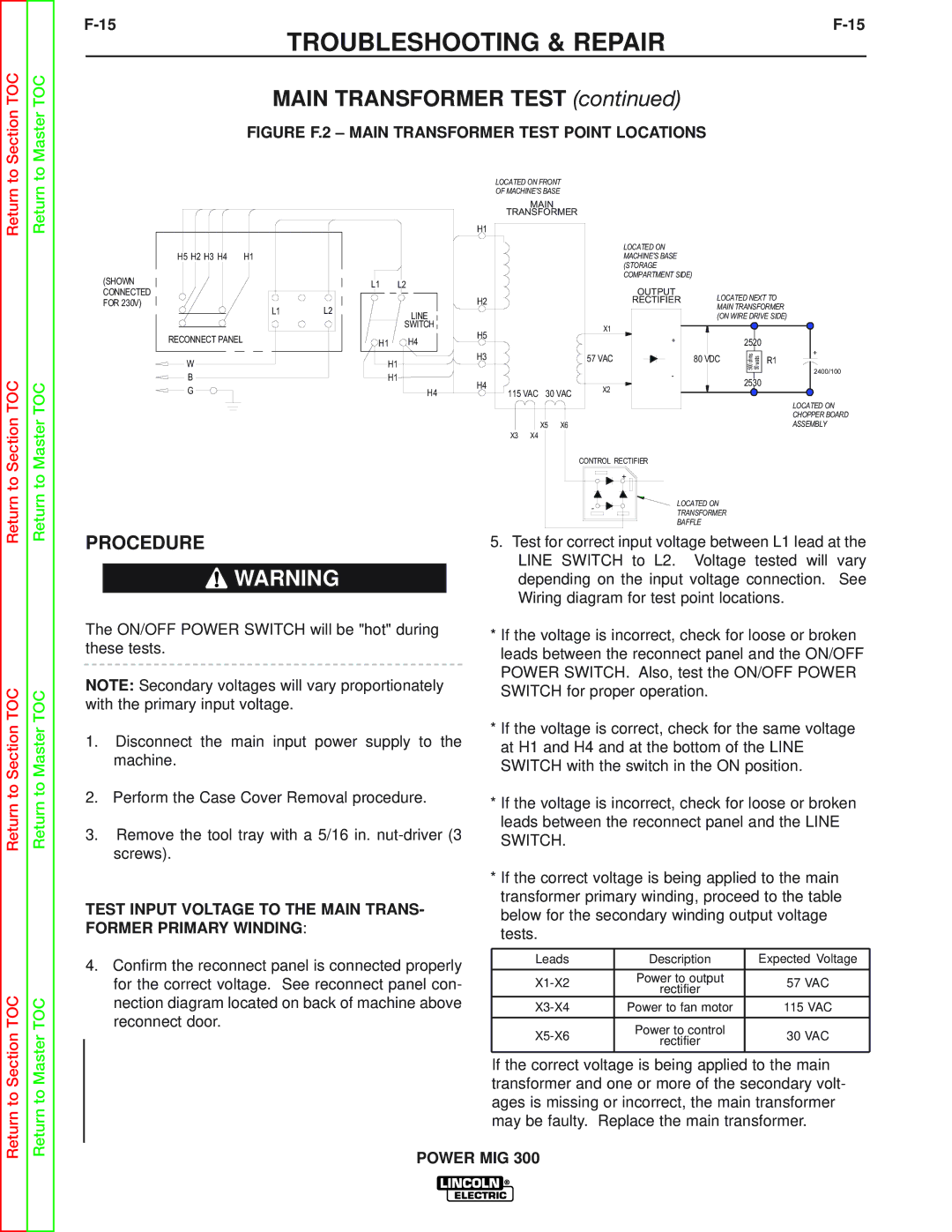
FIGURE F.2 – MAIN TRANSFORMER TEST POINT LOCATIONS

Return

Return to Section TOC

Return

Return to Master TOC

H5 H2 H3 H4

H1

(SHOWN CONNECTED

FOR 230V)

L1L2

RECONNECT PANEL

W

B

G

L1

L2


LINE


SWITCH

H1

H4

H1

H1

H4

LOCATED ON FRONT

OF MACHINE'S BASE

MAIN

TRANSFORMER

H1


LOCATED ON


MACHINE'S BASE


(STORAGE


COMPARTMENT SIDE)


OUTPUT

LOCATED NEXT TO

H2


RECTIFIER


MAIN TRANSFORMER


(ON WIRE DRIVE SIDE)

H5


X1


+


2520


H3


57 VAC


80 VDC

s


+


h a


o


m t


s

R1


0 w


t


0

0


5

5

2400/100


-


H4


2530


X2


115 VAC 30 VAC


LOCATED ON


CHOPPER BOARD


X5 X6


ASSEMBLY

X3

X4


CONTROL RECTIFIER


+


-

LOCATED ON


TRANSFORMER


BAFFLE

Return to Section TOC

Return to Section TOC

Return to Master TOC

Return to Master TOC

PROCEDURE

WARNING

The ON/OFF POWER SWITCH will be "hot" during these tests.

NOTE: Secondary voltages will vary proportionately with the primary input voltage.

1.Disconnect the main input power supply to the machine.

2.Perform the Case Cover Removal procedure.

3.Remove the tool tray with a 5/16 in. nut-driver (3 screws).

TEST INPUT VOLTAGE TO THE MAIN TRANS- FORMER PRIMARY WINDING:

4.Confirm the reconnect panel is connected properly for the correct voltage. See reconnect panel con- nection diagram located on back of machine above reconnect door.

5.Test for correct input voltage between L1 lead at the LINE SWITCH to L2. Voltage tested will vary depending on the input voltage connection. See Wiring diagram for test point locations.

*If the voltage is incorrect, check for loose or broken leads between the reconnect panel and the ON/OFF POWER SWITCH. Also, test the ON/OFF POWER SWITCH for proper operation.

*If the voltage is correct, check for the same voltage at H1 and H4 and at the bottom of the LINE SWITCH with the switch in the ON position.

*If the voltage is incorrect, check for loose or broken leads between the reconnect panel and the LINE SWITCH.

*If the correct voltage is being applied to the main transformer primary winding, proceed to the table below for the secondary winding output voltage tests.

Leads

Description

Expected Voltage


X1-X2

Power to output

57 VAC

rectifier


X3-X4

Power to fan motor

115 VAC


X5-X6

Power to control

30 VAC

rectifier


If the correct voltage is being applied to the main transformer and one or more of the secondary volt- ages is missing or incorrect, the main transformer may be faulty. Replace the main transformer.

POWER MIG 300

Page 59
Image 59
Lincoln Electric SVM160-B service manual Main Transformer Test, Rectifier

SVM160-B specifications

The Lincoln Electric SVM160-B is a standout model in the realm of portable arc welders, designed specifically for light to medium-duty welding tasks. As part of Lincoln Electric’s renowned line of welding equipment, the SVM160-B combines efficiency with durability, catering to both professional welders and hobbyists alike.

One of the primary features of the SVM160-B is its lightweight and compact design. Weighing in at just around 60 pounds, it offers excellent portability, allowing users to easily transport the unit to various job sites. This mobility is enhanced by an integrated handle and a rugged construction, making it suitable for both indoor and outdoor applications.

The SVM160-B utilizes advanced inverter technology, which significantly enhances its performance capabilities. This technology not only contributes to the welder's energy efficiency but also allows for a more stable arc, reducing spatter and resulting in cleaner welds. The machine can operate on both 120V and 240V power sources, providing flexibility for users to adapt to different settings and requirements.

Among its key characteristics, the SVM160-B features a welding output range that accommodates various welding needs, allowing users to achieve welds from 20 to 160 amps. This versatility makes it ideal for welding different materials, including mild steel, stainless steel, and aluminum. Furthermore, the unit supports a range of welding processes, including MIG, stick, and TIG welding, enhancing its adaptability for various projects.

Another highlight of the SVM160-B is its user-friendly interface. The control panel is designed to facilitate ease of use, with clearly marked dials and indicators that enable quick adjustments of settings. This intuitive design ensures that both novice and experienced users can operate the machine efficiently and effectively.

Safety features are also a crucial aspect of the SVM160-B. It comes equipped with thermal overload protection, which prevents the unit from overheating during extended use. This built-in safeguard extends the welder's lifespan and enhances user safety.

In summary, the Lincoln Electric SVM160-B is a versatile, portable welder that combines advanced technology with user-friendly features, making it an excellent choice for a wide range of welding applications. Its lightweight design, inverter technology, and robust safety features make it a reliable option for both professionals and enthusiasts. Whether tackling small repairs or larger projects, the SVM160-B stands ready to deliver quality results.