OPERATION | ||
|
|
|
CONTROLS AND SETTINGS
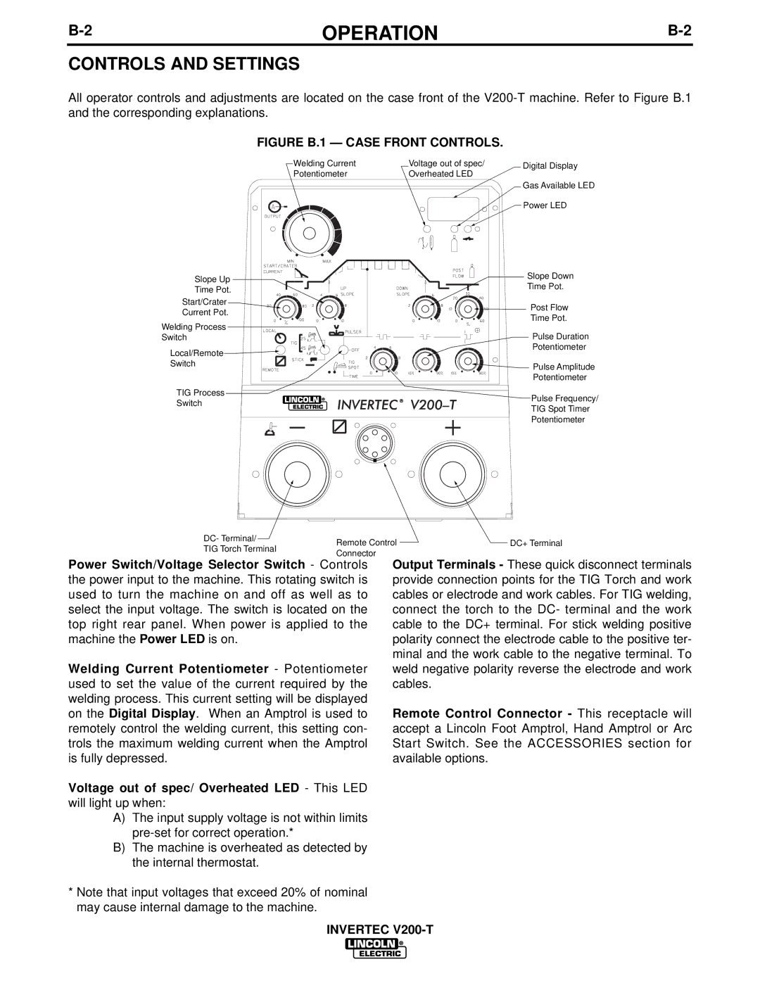
All operator controls and adjustments are located on the case front of the
FIGURE B.1 — CASE FRONT CONTROLS.
Welding Current | Voltage out of spec/ | Digital Display |
Potentiometer | Overheated LED |
|
Gas Available LED
| Power LED | |
Slope Up | Slope Down | |
Time Pot. | ||
Time Pot. | ||
| ||
Start/Crater | Post Flow | |
Current Pot. | ||
Time Pot. | ||
Welding Process | ||
Pulse Duration | ||
Switch | ||
Local/Remote | Potentiometer | |
| ||
Switch | Pulse Amplitude | |
| ||
| Potentiometer | |
TIG Process | Pulse Frequency/ | |
Switch | ||
TIG Spot Timer | ||
| ||
| Potentiometer |
DC- Terminal/ | Remote Control | DC+ Terminal | |
TIG Torch Terminal | |||
Connector |
| ||
|
|
Power Switch/Voltage Selector Switch - Controls the power input to the machine. This rotating switch is used to turn the machine on and off as well as to select the input voltage. The switch is located on the top right rear panel. When power is applied to the machine the Power LED is on.
Welding Current Potentiometer - Potentiometer used to set the value of the current required by the welding process. This current setting will be displayed on the Digital Display. When an Amptrol is used to remotely control the welding current, this setting con- trols the maximum welding current when the Amptrol is fully depressed.
Voltage out of spec/ Overheated LED - This LED will light up when:
A)The input supply voltage is not within limits
B)The machine is overheated as detected by the internal thermostat.
*Note that input voltages that exceed 20% of nominal may cause internal damage to the machine.
Output Terminals - These quick disconnect terminals provide connection points for the TIG Torch and work cables or electrode and work cables. For TIG welding, connect the torch to the DC- terminal and the work cable to the DC+ terminal. For stick welding positive polarity connect the electrode cable to the positive ter- minal and the work cable to the negative terminal. To weld negative polarity reverse the electrode and work cables.
Remote Control Connector - This receptacle will accept a Lincoln Foot Amptrol, Hand Amptrol or Arc Start Switch. See the ACCESSORIES section for available options.
INVERTEC
