INSTALLATION | ||
|
|
|
a)A metal underground water pipe in direct con- tact with the earth for ten feet or more.
b)A 3/4” (19mm) galvanized pipe or a 5/8” (16mm) solid galvanized iron, steel or copper rod driven at least eight feet into the ground.
The ground should be securely made and the ground- ing cable should be as short as possible using cable of the same size as the work cable, or larger. Grounding to the building frame electrical conduit or a long pipe system can result in
6.Keep cover and all screws securely in place.
7.Electrical conductors within 50 ft (15.2m) of the welder should be enclosed in grounded rigid metal- lic conduit or equivalent shielding, wherever possi- ble. Flexible metallic conduit is generally not suit- able.
8.When the welder is enclosed in a metal building, the metal building should be connected to several good earth driven electrical grounds (as in 5 (b) above) around the periphery of the building.
Failure to observe these recommended installation procedures can cause radio or TV and electronic equipment interference problems and result in unsat- isfactory welding performance resulting from lost high frequency power.
INPUT CONNECTIONS
Be sure the voltage, phase, and frequency of the input power is as specified on the rating plate, located on the rear of the machine.
Supply line entry provision is in the case rear panel.
A power cord is provided and wired into the machine. Follow the power cord connection instructions. Incorrect connection may result in equipment damage.
The Invertec
To connect the
1.Disconnect the machine from the input supply.
2.Remove the wraparound by removing the shoul- der strap brackets and wraparound screws.
3.Provide access to the line switch by bending the insulation back.
4.When the insulation is bent back, two sleeved leads will become visible.
5.Remove the sleeving from both leads.
6.Connect the large lead to
7.Connect the small lead to terminal 15 of the line switch.
8.Reposition insulation to cover line switch.
9.
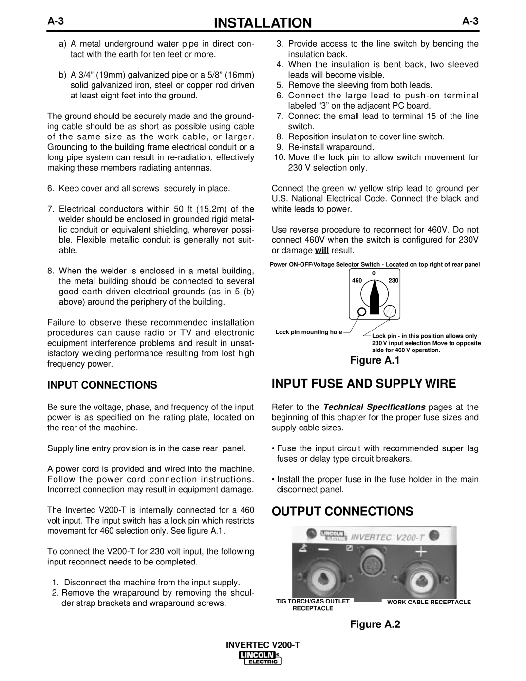
10.Move the lock pin to allow switch movement for 230 V selection only.
Connect the green w/ yellow strip lead to ground per U.S. National Electrical Code. Connect the black and white leads to power.
Use reverse procedure to reconnect for 460V. Do not connect 460V when the switch is configured for 230V or damage will result.
Power
0
460230
Lock pin mounting hole
Lock pin - in this position allows only 230 V input selection Move to opposite side for 460 V operation.
Figure A.1
INPUT FUSE AND SUPPLY WIRE
Refer to the Technical Specifications pages at the beginning of this chapter for the proper fuse sizes and supply cable sizes.
•Fuse the input circuit with recommended super lag fuses or delay type circuit breakers.
•Install the proper fuse in the fuse holder in the main disconnect panel.
OUTPUT CONNECTIONS
TIG TORCH/GAS OUTLET |
| WORK CABLE RECEPTACLE |
RECEPTACLE |
|
|
|
|
Figure A.2
INVERTEC